


5.6 Motor Direction Setting
5-18
5.6
Motor Direction Setting
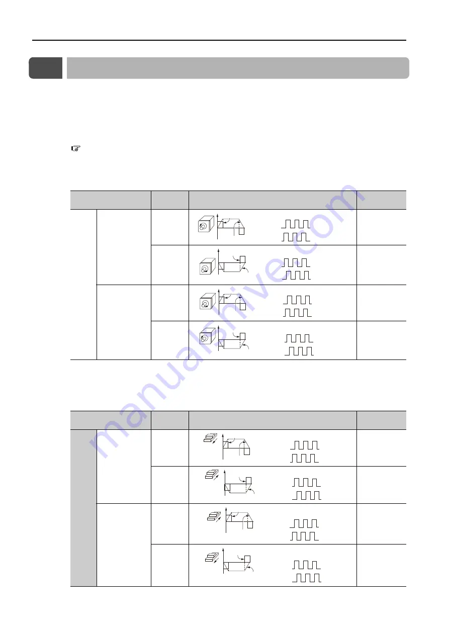
You can reverse the direction of Servomotor rotation by changing the setting of Pn000 =
n.
X (Direction Selection) without changing the polarity of the speed or position reference.
This causes the rotation direction of the motor to change, but the polarity of the signals, such
as encoder output pulses, output from the SERVOPACK do not change. Set the appropriate
direction for your system.
Refer to the following section for details on the encoder divided pulse output.
6.8 Encoder Divided Pulse Output
•
Rotary Servomotors
The default setting for forward rotation is counterclockwise (CCW) as viewed from the load end
of the Servomotor.
Note: The trace waveforms of the S are shown in the above table for the torque reference and motor speed diagrams. If you
measure them on a measuring instrument, e.g., with an analog monitor, the polarity will be reversed.
‘
•
Linear Servomotors
Before you set this parameter, make sure that Pn080 = n.
X
(Motor Phase Sequence
Selection) is set correctly.
Note: The trace waveforms of the S are shown in the above table for the force reference and motor speed diagrams. If you mea-
sure them on a measuring instrument, e.g., with an analog monitor, the polarity will be reversed.
Parameter
Forward/Reverse
Reference
Motor Direction and Encoder Divided Pulse Outputs
Applicable
Overtravel Signal (OT)
Pn000
n.
0
Use CCW as
the forward
direction.
(default setting)
Forward
reference
P-OT (For-
ward Drive
Prohibit) signal
Reverse
reference
N-OT
(Reverse Drive
Prohibit) signal
n.
1
Use CW as the
forward direc-
tion.
(Reverse Rota-
tion Mode)
Forward
reference
P-OT (For-
ward Drive
Prohibit) signal
Reverse
reference
N-OT
(Reverse Drive
Prohibit) signal
Parameter
Forward/Reverse
Reference
Motor Moving Direction and Encoder Divided Pulse
Outputs
Applicable
Overtravel Signal (OT)
Pn000
n.
0
Use the direc-
tion in which
the linear
encoder counts
up as the for-
ward direction.
(default setting)
Forward
reference
P-OT (For-
ward Drive
Prohibit) signal
Reverse
reference
N-OT
(Reverse Drive
Prohibit) signal
n.
1
Use the direc-
tion in which
the linear
encoder counts
down as the
forward direc-
tion.
Forward
reference
P-OT (For-
ward Drive
Prohibit) signal
Reverse
reference
N-OT
(Reverse Drive
Prohibit) signal
Motor
s
peed
Time
Torque reference
CCW
+
Encoder Divided Pul
s
e Output
s
Pha
s
e-B lead
PAO
PBO
Torque reference
Motor
s
peed
Time
CW
+
Encoder Divided Pul
s
e Output
s
Pha
s
e-A lead
PAO
PBO
Torque reference
Time
Motor
s
peed
CW
+
Encoder Divided Pul
s
e Output
s
Pha
s
e-B lead
PAO
PBO
Torque reference
Time
Motor
s
peed
CCW
+
Pha
s
e-A lead
Encoder Divided Pul
s
e Output
s
PAO
PBO
Force reference
Motor
s
peed
Time
Move
s
in the
count-up
direction.
+
Encoder Divided Pul
s
e Output
s
Pha
s
e-B lead
PAO
PBO
Move
s
in the
count-down
direction.
Force reference
Motor
s
peed
Time
+
Encoder Divided Pul
s
e Output
s
Pha
s
e-A lead
PAO
PBO
Force reference
Motor
s
peed
Time
Move
s
in the
count-down
direction.
+
Encoder Divided Pul
s
e Output
s
Pha
s
e-B lead
PAO
PBO
Move
s
in the
count-up
direction.
Force reference
Time
Motor
s
peed
+
Encoder Divided Pul
s
e Output
s
Pha
s
e-A lead
PAO
PBO


