6-17
166006-1CD
166006-1CD
6
Maintenance and Inspection
6.8 Tooling Axis Reduction Gear Units (RV–80E–X)
RM2-755/1255SL
Positioner
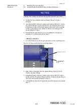
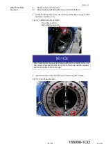
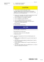
10. Install the rest of the M16 screws for the ring gear and torque to
255Nm.
11. Repeat
6.7.1.2 Positioner Production Prior to October 2018
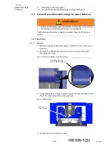
The backlash between the drive pinion and the ring gear needs to be set
at 0.110mm to 0.140mm. Setting the backlash requires adding or
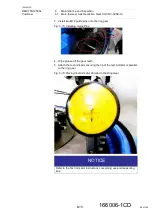
removing shims under the sweep axis motor assembly. An indicator gauge
needs to be positioned to measure the pitch line movement of the
meshing gears. The actual measurement is the free movement of the
gears.
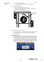
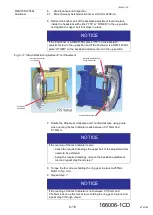
Set the backlash at the high spots of both gears. The ring gear is marked
with paint and 3 x 0's on the teeth, while the pinion is marked on the face
with three center punch marks.
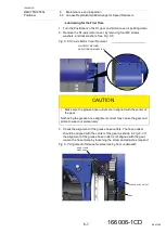
If tooling is present on the Positioner, rotate the Positioner to have the
motor at the top (B side at operator) and block both sides to prevent
movement. Position the first indicator to measure the pinion gear pitch line
movement. Position a second indicator to the swing arm and touch the
ring gear pitch line. With the programming pendent, rotate the S1-motor in
single pulse mode, and measure the movement of the pinion gear until
there is movement of the ring gear.
When backlash is set re-torque the bracket retaining bolts and re-check
the lash. Torque of the retaining bolts to 490Nm.
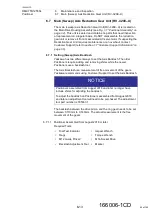
6.8 Tooling Axis Reduction Gear Units (RV–80E–X)
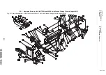
Two Reduction Gear Units (RV–80E–X) are located in the Tooling Drive
Swingarm Assembly, one for each tooling plate (see
). These units are sealed and contain no parts that
need inspection or replacement on a regular basis. Do NOT disassemble
the reduction gear unit or remove it from its associated AC servomotor. If
suspecting the Reduction Gear Unit requires maintenance or an overhaul,
contact Customer Support.
section 1.7 “Customer Support Information” on page 1-6
).
6.9 Main (Swing) Axis Hardstops
The Positioner incorporates two buffered hardstops that are welded to the
Tooling Drive Swingarm Assembly. The hardstops provide a positive stop
for the 755 Tailstock Tooling Drive Swingarm Assembly (and thus the Arc
Shield and Main Axis Swingarm Assembly) during a sweep cycle. The
1255SL tailstock hardstop is fixed while the headstock is adjustable. The
adjustable hardstops must be set at the finial installation process and are
located on the headstock. Refer to
section 2.6 “Adjusting the Hardstops”
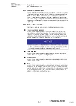
NOTICE
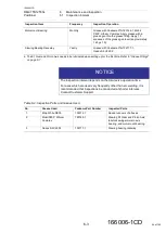
If the reading of the test indicator is not between 0.110mm and
0.140mm remove the M16
EXCEPT FOR
the original four screws
holding the ring gear in place and repeat
through
.
68 of 145

