1.7 H: Terminal Functions
176
YASKAWA ELECTRIC
SIEP C710606 10A YASKAWA AC Drive - V1000 PRELIM. Programming Manual
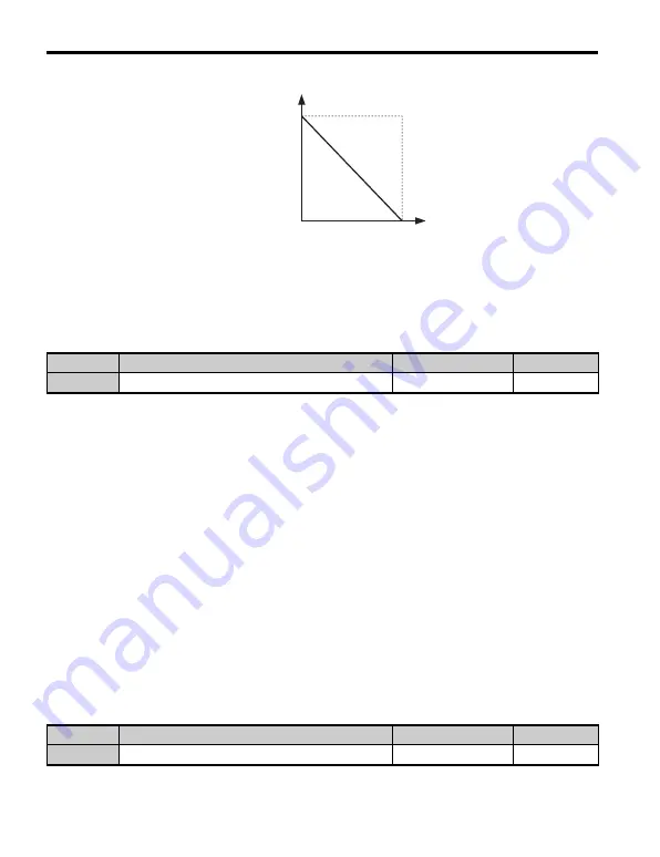
Figure 1.70
Figure 1.70 Frequency Reference Setting by Analog Input with Inverse Gain and Bias Settings
■
H3-09: Terminal A2 Signal Level Selection
Selects the input signal level for analog input A2. Be sure to also set DIP switch S1 on the
terminal board accordingly for a voltage input or current input.
Setting 0: 0 to 10 Vdc with Limit
The input level is 0 to 10 Vdc. Negative input values will be limited to 0. Refer to the
explanation of H3-01, Setting 0.
Setting 1: 0 to 10 Vdc without Limit
The input level is 0 to 10 Vdc. Negative input values will be accepted. Refer to the
explanation of H3-01, Setting 1.
Setting 2: 4 to 20 mA Current Input
The input level is 4 to 20 mA. Negative input values by negative bias or gain settings will be
limited to 0 (like setting 0).
Setting 3: 0 to 20 mA Current Input
The input level is 0 to 20 mA. Negative input values by negative bias or gain settings will be
limited to 0 (like setting 0).
■
H3-10: Terminal A2 Function Selection
Determines the function assigned to analog output terminal A2. Refer to
Analog Input Terminal Settings on page 177
for a list of functions and descriptions.
No.
Name
Setting Range
Default
H3-09
Terminal A2 Signal Level Selection
0 to 3
2
No.
Name
Setting Range
Default
H3-10
Terminal A2 Function Selection
0 to 31
0
0 V
10 V
Gain = 0 %
Bias = 100 %
Frequency
reference
Содержание OYMC V1000
Страница 2: ...2 YASKAWA ELECTRIC SIEP C710606 10A YASKAWA AC Drive V1000 PRELIM Programming Manual...
Страница 8: ...8 YASKAWA ELECTRIC SIEP C710606 10A YASKAWA AC Drive V1000 PRELIM Programming Manual INDEX 393...
Страница 294: ...2 12 Self Diagnostics 294 YASKAWA ELECTRIC SIEP C710606 10A YASKAWA AC Drive V1000 PRELIM Programming Manual...
Страница 407: ...YASKAWA ELECTRIC SIEP C710606 10A YASKAWA AC Drive V1000 PRELIM Programming Manual 407...


