


5
Disassembly and Reassembly of the Motor
5.4
Disassembly and Reassembly of the R-Axis Motor
5-16
HW1484673
HW1484673
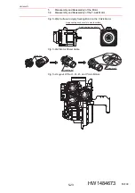
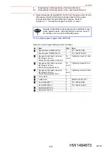
7. As shown in
fig. 5-6(d) “Motor Power Cable”
, insert the power
connector to the R-axis motor
by aligning the key position, and then
turn the coupling nut on the cable side until it makes a clicking sound.
Confirm that the arrow marks on the connector on the motor side and
the connector on the wiring harness side match.
8. Turn ON the power supply of the YRC1000.
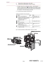
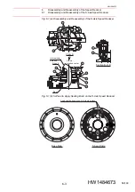
Fig. 5-6(a): Disassembly and Reassembly of the R-Axis Motor
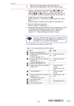
Table 5-5: R-Axis Motor Parts Checklist
No.
Item
Qty.
Note
R-axis motor HW1385163-A
1
SGM7G-09APK-YR1*
Hexagon socket head cap screw M8
(length: 25 mm) *trivalent chromate*
Conical spring washer 2H-8
*trivalent chromate*
3 each
Tightening torque 24.5
N•m
Key
1
Provided with the motor
Gear HW0313626-1
1
Bearing 6003
1
Hexagon socket head cap screw M6
(length: 50 mm)
Conical spring washer 2L-6
1 each
Tightening torque 16.5
N•m
Retaining ring ISTW17
1
Slim head screw M4 (length: 6 mm)
*trivalent chromate*
3
Tightening torque 0.75
N•m
1
1
2
3
4
5
6
7
8
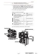
R-axis
Apply sealing bond here.
T-axis
B-axis
R-axis
U-axis
Casing
R-axis rotation center
1
8 2
3
4
5
7
6
Without bolt
Without screw
Tapped hole for motor and spacer
(4 places)
48/109