5.8 LED Indicators on the Controller and Cell Control Board
YASKAWA ELECTRIC
TOEP C710687 02B FSDrive-MV1000 Instructions
177
T
ro
ubles
hoo
ting
5
5.8 LED Indicators on the Controller and Cell Control Board
The following section describes the LED indicators on the controller in the control panel and on the Cell Control Board
(CCB) in the Power Cell panel. These indicators display operation statuses and faults.
u
LED Indicators on the Controller
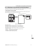
The controller has two types of LED indicators: An LED indicator that displays the controller status, and an LED
indicator that displays the Power Cell status detected by the controller.
Figure 5.1
Figure 5.1 LED on Controller
Power Cell Status LEDs:
PH_A RANK1 to 5 (Red): Lit when a phase-U rank 1 to 5 Power Cell fault occurs.
PH_B RANK1 to 5 (Red): Lit when a phase-V rank 1 to 5 Power Cell fault occurs.
PH_C RANK1 to 5 (Red): Lit when a phase-W rank 1 to 5 Power Cell fault occurs.
BYPS RANK1 to 5 (Red): Lit when a fault occurs in a rank 1 to 5 Power Cell for bypass.
• Controller Status LEDs
BAT (Red): Lit when the voltage of the battery housed in the controller drops.
ERR (Red): Lit when a fault occurs in the controller.
RUN (Green): Lit during operation of the controller.
PWR (Green): Lit when the controller is powered on.
Controller
Drive panel
<Position of the controller>
<Status with the controller drawn out>
470
'44
294
2*A%
$#6
2*A$
$;25
2*A#
4#0- 4#0- 4#0- 4#0- 4#0-
Controller
(Draw-out
construction)
%$
%$
%$
%$
%$
%$
%$
%$
ᵈᗧ
ᵈᗧ
%#76+10
%#76+10
ᵈᗧ
ᵈᗧ
%#76+10
%#76+10
ᵈᗧ
ᵈᗧ
%#76+10
%#76+10
ᵈᗧ
ᵈᗧ
%#76+10
%#76+10
ᵈᗧ
ᵈᗧ
%#76+10
%#76+10
ᵈᗧ
ᵈᗧ
%#76+10
%#76+10
ᵈᗧߊߛߐޕ
ᵈᗧߊߛߐޕ
2NGCUGFQPQVECVEJVJGHKPIGT
2NGCUGFQPQVECVEJVJGHKPIGT
DGVYGGPRCPGNHNCOGCPFVJKUWPKV
DGVYGGPRCPGNHNCOGCPFVJKUWPKV
ޓࡄࡀ࡞ࡈ㧙ࡓߣᧄ࡙࠾࠶࠻ߣߩ㑆ߢᜰࠍ߹ߥࠃ߁ߦ
ޓࡄࡀ࡞ࡈ㧙ࡓߣᧄ࡙࠾࠶࠻ߣߩ㑆ߢᜰࠍ߹ߥࠃ߁ߦ
ޓャㅍᤨߩࡂࡦ࠼࡞ᛮߌ㒐ᱛ↪ߦࡄࡀ࡞ࡈ㧙ࡓⓣߣࡂࡦ࠼࡞
ޓャㅍᤨߩࡂࡦ࠼࡞ᛮߌ㒐ᱛ↪ߦࡄࡀ࡞ࡈ㧙ࡓⓣߣࡂࡦ࠼࡞
ߩ㑆ߦ⚿᧤ࡃࡦ࠼╬ࠍᏎ߈ઃߌߡਅߐޕ
ߩ㑆ߦ⚿᧤ࡃࡦ࠼╬ࠍᏎ߈ઃߌߡਅߐޕ
2NGCUGFQPQVECVEJVJGHKPIGT
2NGCUGFQPQVECVEJVJGHKPIGT
DGVYGGPRCPGNHNCOGCPFVJKUWPKV
DGVYGGPRCPGNHNCOGCPFVJKUWPKV
Asia
Содержание FSDrive-MV1000 Series
Страница 8: ...8 YASKAWA ELECTRIC TOEP C710687 02B FSDrive MV1000 Instructions...
Страница 38: ...1 4 Component Names and Configurations 38 YASKAWA ELECTRIC TOEP C710687 02B FSDrive MV1000 Instructions...
Страница 106: ...3 9 Wiring Check 106 YASKAWA ELECTRIC TOEP C710687 02B FSDrive MV1000 Instructions...
Страница 136: ...4 9 Checking and Saving Parameter Default Values 136 YASKAWA ELECTRIC TOEP C710687 02B FSDrive MV1000 Instructions...
Страница 210: ...6 7 Spare Parts 210 YASKAWA ELECTRIC TOEP C710687 02B FSDrive MV1000 Instructions...
Страница 222: ...B 1 European Standards 222 YASKAWA ELECTRIC TOEP C710687 02B FSDrive MV1000 Instructions...


