8.13 Manual Tuning
8.13.1 Tuning the Servo Gains
8-73
8
T
uning
8.13
Manual Tuning
This section describes manual tuning.
8.13.1
Tuning the Servo Gains
Servo Gains
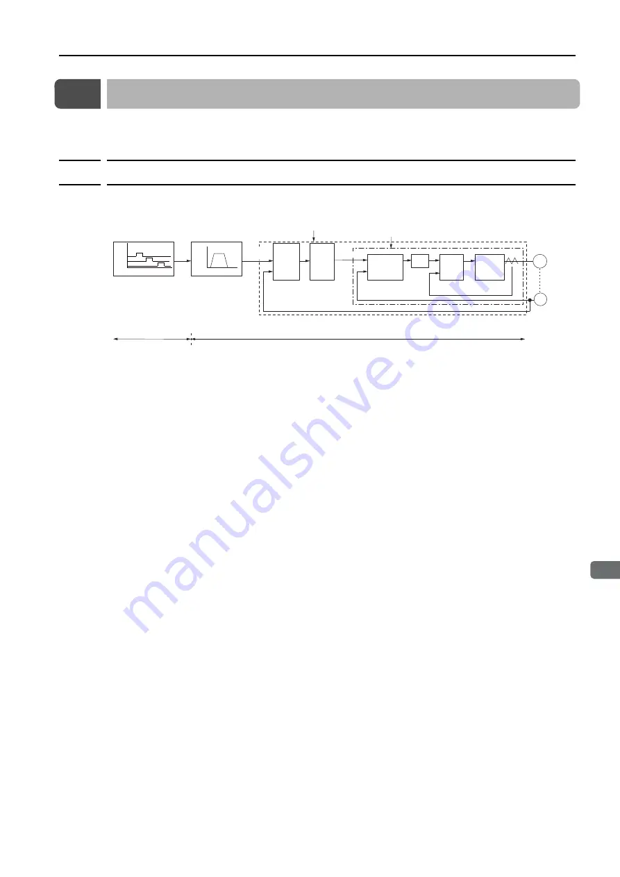
In order to manually tune the servo gains, you must understand the configuration and charac-
teristic of the SERVOPACK and adjust the servo gains individually. In most cases, if you greatly
change any one parameter, you must adjust the other parameters again. To check the
response characteristic, you must prepare a measuring instrument to monitor the output wave-
forms from the analog monitor.
The SERVOPACK has three feedback systems (the position loop, speed loop, and current
loop), and the response characteristic must be increased more with the inner loops. If this rela-
tionship is not maintained, the response characteristic will suffer and vibration will occur more
easily.
A sufficient response characteristic is ensured for the current loop. There is never a need for it
to be adjusted by the user.
Outline
You can use manual tuning to set the servo gains in the SERVOPACK to increase the response
characteristic of the SERVOPACK and to reduce the positioning time.
Use manual tuning in the following cases.
•
When tuning with autotuning without a host reference or autotuning with a host reference
does not achieve the desired results
•
When you want to increase the servo gains higher than the gains that resulted from autotun-
ing without a host reference or autotuning with a host reference
•
When you want to determine the servo gains and moment of inertia ratio yourself
You start manual tuning either from the default parameter settings or from the gain settings that
resulted from autotuning without a host reference or autotuning with a host reference.
Encoder
Position control loop
Speed control loop
Speed Speed pattern
Time
Deviation
counter
Position
loop
gain
Kp
Speed control
section
Kv and Ti
+
-
Current
control
section
Power
converter
Servomotor
M
PG
Position loop
SERVOPACK
Program table
Host controller
(Not provided by Yaskawa)
Kp: Position loop gain (Pn102)
Kv: Speed loop gain (Pn100)
Ti: Speed loop integral time constant (Pn101)
Tf: First stage first torque reference filter time constant (Pn401)
Input
Signals
+
-
+
-
Speed loop
Current loop
Tf
Time
Input pattern
Input
Movement
reference
Speed
reference


