


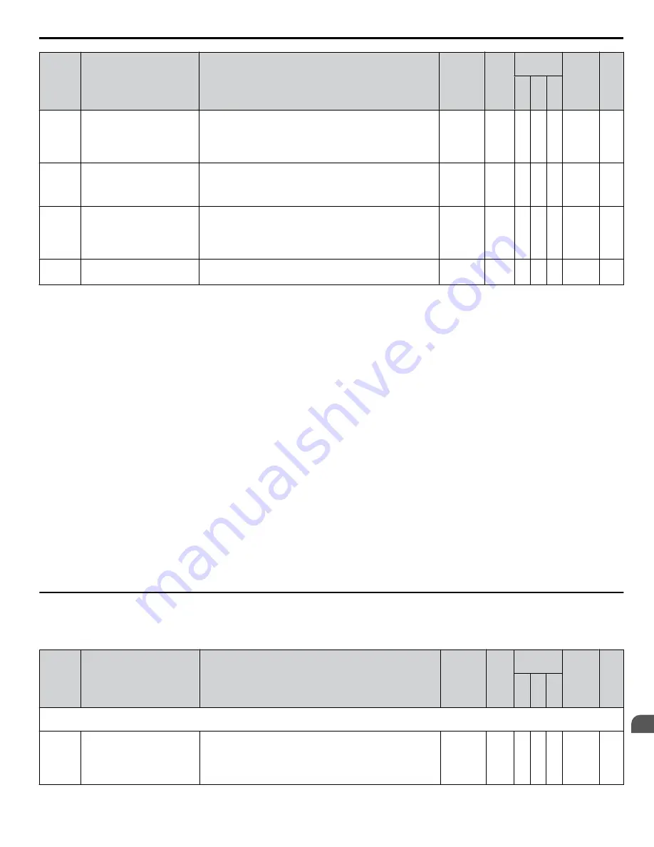
No.
Name
Description
Range
Def.
Control
Mode
Addr.
Hex
Pg.
V/
f
O
L
V
P
M
L8-40
Carrier Frequency Reduction
Time
Sets the time for that the drive continues running with reduced
carrier frequency after the carrier reduction condition has gone
(see also L8-38).
A setting of 0.00 s disables the carrier frequency reduction
time.
0.00 to
2.00
0.50
A A A
4F1
L8-41
High Current Alarm Selection
Configures an alarm when the output current exceeds 150% of
the drive rated current.
0: Alarm disabled.
1: Alarm enabled.
0, 1
0
A A A
4F2
L8-51
<14>
STo Fault Detection Level
Sets the STo detection level as a percentage of the motor rated
current.
Increase this value to detect pull-out more quickly during
acceleration. The drive calculates this value automatically
when L8-51 is set to 0.0%.
0.0 to
150.0%
0.0% –
– A
471
L8-54
<14>
STo Deviation Detection
0: Disabled.
1: Enabled.
0, 1
1
–
– A
474
<1> Setting 6 available in drive software versions PRG: 1016 and later.
<2> Default setting value is dependent on parameter A1-02, Control Method Selection. The value shown is for A1-02 = 0-V/f Control.
<3> Default setting value is dependent on parameter o2-04, Drive Model Selection.
<4> Default setting value is dependent on parameter o2-04, Drive Model Selection and C6-01, Drive Duty Selection.
<5> Values shown here are for 200 V class drives. Double the value when using a 400 V class drive.
<6> Default setting value is dependent on parameter E1-01, Input Voltage Setting.
<7> Setting value 2 is not available A1-02 = 5-PM OLV Control. When enabled, the drive stops accelerating when it exceeds the value of L3-02, Stall
Prevention Level. The drive decelerates after 100 ms and begins accelerating again after restoring the current level.
<8> Default setting value is 120% when C6-01 is set to 1 (ND) and 150% when C6-01 is set to 0 (HD).
<9> The setting range depends on the control mode set in A1-02. For PM OLV Control the setting range is 0 to 2 and 7.
<10> Default setting value is dependent on parameter E5-01, Motor Code Selection.
<11> Parameter value is changed if E2-11 is manually changed or changed by Auto-Tuning.
<12> Available in drive software versions PRG: 1016 and later.
<13> Parameter setting value is not reset to the default value during drive initialization, A1-03 = 1110, 2220, 3330.
<14> Available in drive software versions PRG: 1018 and later. There is normally no need to change this parameter from the default value.
<15> Default setting is determined by drive software version and C6-02 setting. Drive software versions PRG: 1021 and later have a default setting of 0
when the carrier frequency is set for Leakage Current Rejection PWM (C6-02 = B), and 1 when C6-02 is set to any other value.
<16> Parameter can be changed during Run.
<17> Available in drive software versions PRG: 1021 and later.
<18> The default setting and the upper limit of the setting range are determined by C6-01, Drive Duty Mode, and L8-38, Carrier Frequency Reduction
Selection.
u
n: Advanced Performance Set-Up
The n parameters are used to adjust more advanced performance characteristics such as hunting prevention, speed feedback
detection, high-slip braking and R1 online tuning.
No.
Name
Description
Range
Def.
Control
Mode
Addr.
Hex
Pg.
V/
f
O
L
V
P
M
n1: Hunting Prevention
Use n1 parameters to configure hunting prevention operation.
n1-01
Hunting Prevention Selection
If the motor vibrates while lightly loaded, Hunting Prevention
may reduce the vibration.
0: Disabled
1: Enabled
When quick response is needed disable Hunting Prevention.
0, 1
1
A −
−
580
B.2 Parameter Table
YASKAWA ELECTRIC SIEP C710606 18F YASKAWA AC Drive – V1000 Technical Manual
391
B
Parameter List