background image

PRODUCT OVERVIEW

SD60 Operation Manual

11

NOTICE

The anode of the Sail-Drive is only 
calculated for the Sail-Drive. Changing the 
material of the propeller may require 
additional anodes to be installed on the 
Sail-Drive.

NOTICE

Failure to use the correct anode material 
may result in inadequate protection and 
excessive corrosion of underwater drive 
system components. Use only aluminum 
anodes in brackish and saltwater 
applications. In freshwater applications, 
use aluminum or magnesium anodes for 
best results. Never use magnesium 
anodes in brackish or salt water, as they 
will deteriorate rapidly, which will lead to 
severe damage to the drive system.

If sacrificial anodes erode quickly or if 
signs of corrosion are evident, the owner 
should take immediate corrective action. 
Yanmar recommends consulting an 
engineer specializing in marine electricity 
and corrosion control to determine the best 
way to correct the rapid erosion of the 
anodes.

Electrical Connections and 
Regulations According to 
International Rules ISO 
60092-507 IEC:2008

It is recommended to perform the boat 
electric system in conformity with the 
regulation ISO 60092-507 IEC 2008, or 
equal local and international rules or laws.

To protect the boat from galvanic current 
when it is connected to the power source 
located on the dry land (wharf), it is 
recommended to install on the boat a 
galvanic isolator on the ground conductor 
of the AC power line.

This will prevent the flow of galvanic 
current with low voltage but will allow a 
normal supply.

For more information about or to find 
different solutions of the power system 
from the dry land, refer to the instructions 
of ABYC (American Boat and Yacht 
Council) in chapter E-11 or ISO 60092-507 
IEC 2008.

At the same purpose can also be used an 
isolating transformer with the relevant 
characteristics of the circuit. Even in this 
case, refer to the applicable ABYC E-11 or 
ISO 60092-507 IEC 2008 for more 
information and suggestions.

Note: We advise you to install an isolating 

transformer for the electrical power 
supply from pier.

SHORE POWER

Vessels that are connected to shore power 
require additional protection to prevent 
destructive low voltage galvanic currents 
from passing through the shore power 
ground wire. Galvanic isolators are 
available from the aftermarket (not 
supplied by Yanmar) to block these 
currents while still providing a path to 
ground for dangerous shock currents.

NOTICE

If the AC shore power ground is not 
isolated from the boat ground, sacrificial 
anodes may be unable to neutralize the 
increased galvanic potential. Corrosion 
damage that results from the improper 
system design or application is not 
covered by the Yanmar Limited Warranty.

SD60_OPM.book  11 ページ  2017年12月8日 金曜日 午後3時6分

Содержание SD60

Страница 1: ...English en English OPERATION MANUAL SAIL DRIVE SD60...

Страница 2: ...reserve the right to make any change at any time without notice Yanmar and are registered trademarks of YANMAR CO LTD in Japan the United States and or other countries All Rights Reserved No part of...

Страница 3: ...ew 9 Owner Operator Responsibilities 9 New Sail Drive Break In 9 Dealer Distributor Responsibilities 9 Galvanic Corrosion 10 Corrosion Control 10 Electrical Connections and Regulations According to In...

Страница 4: ...19 Gear Shift Operation 20 Periodic Maintenance 21 Maintenance 22 Routine Maintenance 22 Scheduled Maintenance 22 Maintenance Procedures 23 Oil Level Check 23 Oil Change 24 Removing Propeller 27 Inst...

Страница 5: ...ndling and operation refer to the respective Operation Manuals for Engine Models JH series in the below table However instructions for the marine gear box are not necessary as they are included Engine...

Страница 6: ...INTRODUCTION 2 SD60 Operation Manual This Page Intentionally Left Blank SD60_OPM book 2...

Страница 7: ...serious injury WARNING Indicates a hazardous situation which if not avoided could result in death or serious injury CAUTION Indicates a hazardous situation which if not avoided could result in minor...

Страница 8: ...service the Sail Drive to ensure that you follow safe operating practices and maintenance procedures Safety signs and labels are additional reminders for safe operating and maintenance techniques See...

Страница 9: ...ive while under tow or if the engine is running at idle speed The propeller may rotate under these circumstances Never wear jewelry unbuttoned cuffs ties or loose fitting clothing and always tie long...

Страница 10: ...efore beginning service WARNING Exhaust Hazard Never block windows vents or other means of ventilation if the engine is operating in an enclosed area All internal combustion engines create carbon mono...

Страница 11: ...ly checks as listed in this Operation Manual Periodic maintenance prevents unexpected downtime reduces the number of accidents due to poor Sail Drive performance and can help extend the life of the Sa...

Страница 12: ...tions In freshwater applications use aluminum or magnesium anodes for best results Never use magnesium anodes in brackish or salt water as they will deteriorate rapidly which will lead to severe damag...

Страница 13: ...ce service condition Monitor conditions frequently to determine if the maintenance intervals suggested in the manual are frequent enough for your Sail Drive New Sail Drive Break In On the initial engi...

Страница 14: ...orrosion and replace the anodes often enough to provide a sacrificial surface for the electrical current to attack Galvanic isolators and isolation transformers are also available from the aftermarket...

Страница 15: ...is connected to the power source located on the dry land wharf it is recommended to install on the boat a galvanic isolator on the ground conductor of the AC power line This will prevent the flow of g...

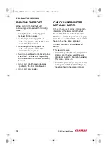
Страница 16: ...heir use Do not paint drain holes or items as specified by the boat manufacturer Do not paint any anodes CHECK UNDER WATER METALLIC PARTS Check the status of corrosion protection boat dry of the lower...

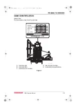
Страница 17: ...IFICATION Name Plate The name plate is fixed onto the sail drive A Sail drive type B Sail drive ratio C Sail drive serial number D Sail drive part number E Lubricating oil specifications Figure 1 1 2...

Страница 18: ...PRODUCT OVERVIEW 14 SD60 Operation Manual This Page Intentionally Left Blank SD60_OPM book 14...

Страница 19: ...nual 15 BEFORE YOU OPERATE This section of the Operation Manual describes lubricating oil specifications and how to replenish them Before you operate the Sail Drive review the Safety section on page 3...

Страница 20: ...ng oil quantity Figure 1 3 Loosen dipstick 1 Figure 1 by turning the grip counterclockwise 4 Wipe dipstick with a clean and dustfree cloth 5 Insert dipstick do not screw Remove dipstick and check lubr...

Страница 21: ...SD60 Operation Manual 17 SAIL DRIVE OPERATION Before you operate the Sail Drive read the following safety information and review the Safety section on page 3 SD60_OPM book 17...

Страница 22: ...e operating temperature considerably Boat Sailing Moving in Tow or Anchoring When the engine is off and the boat sails moves in tow or is anchored the propeller may turn with the water current WARNING...

Страница 23: ...ual 19 Direction of Rotation Shifting to A Propeller rotation Same direction as engine crankshaft Shifting to B Propeller rotation Opposite direction from the engine crankshaft Figure 1 050441 01EN00...

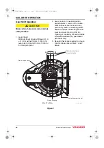
Страница 24: ...erpendicular to control rod or cable Gear shift lever can be fixed in any position by means of clamping screw Minimum distance between gear shift lever and cover 0 5 mm 0 02 in Opening or loosening of...

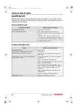
Страница 25: ...e you perform maintenance on the Sail Drive read the following safety information and review the Safety section on page 3 This section of the Operation Manual describes the procedures for proper care...

Страница 26: ...30 days of operation according to the interval that occurs first Interval Maintenance to be Performed After the first 50 hours Change the oil Every 250 hours of operation or once a year according to...

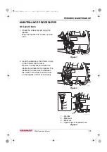
Страница 27: ...t the dipstick so that it rests on top of the threads into the case Remove the dipstick and check the lubricating oil level on the dipstick The lubricating oil level must be between the marks of minim...

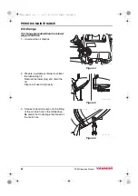
Страница 28: ...re 4 2 Prepare a suitable container to collect the lubricating oil Remove the lower plug and drain the oil Dispose of used oil properly Figure 5 3 Connect a hand oil pump onto the fitting of the oil d...

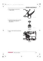
Страница 29: ...pressure pump add oil 3L SAE 15W 40 Figure 7 5 Replace the O rings on the oil cap sail drive lubricate it and prepare to reassemble it Figure 8 6 Screw in the oil dipstick and tighten by hand Figure...

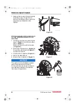
Страница 30: ...rom the oil suction pipe 2 Figure 11 Suction can be done with hand pump 4 Figure 12 2 Push hose of hand pump 4 Figure 12 through the suction pipe 2 Figure 11 and suck the fluid off 3 Un screw the oil...

Страница 31: ...mm allen wrench loosen and remove the locking screw of the bullet Figure 13 2 Insert a suitable tool into the hole Loosen and remove the propeller spinner nut Figure 14 3 Remove the wooden block Remov...

Страница 32: ...eeve Install chamfered side away from propeller Figure 17 2 Put some anti corrosion grease on the grooves of the propeller shaft Figure 18 050911 01X00 050912 01X00 Description Employment Antifouling...

Страница 33: ...ller shaft nut Figure 20 5 Place a block of wood between one of the propeller blades and the hull Mount the special insert T2 on a suitable torque wrench and insert into the hole in the propeller nut...

Страница 34: ...d connection terminal then the system can be treated as an isolated system Non Isolated systems If either the starter motor or the alternator uses a single battery and uses the body or case as a groun...

Страница 35: ...s on board the vessel This replaceable sacrificial anode capacity is for the drive only When a non Aluminium propeller is installed the non Aluminium propeller must have a additional replaceable sacri...

Страница 36: ...PERIODIC MAINTENANCE 32 SD60 Operation Manual 4 Tighten to a torque of 12 N m Figure 25 050920 01X01 SD60_OPM book 32...

Страница 37: ...TALLATION Verify carefully the correct engine grounding NOTICE Grounding is normally connected to the negative pole of the battery An incorrect installation can cause a premature corrosion of the SD60...

Страница 38: ...ELECTRIC INSTALLATION 34 SD60 Operation Manual This Page Intentionally Left Blank SD60_OPM book 34...

Страница 39: ...e performing any troubleshooting procedures within this section review the Safety section on page 3 If a problem occurs stop the engine immediately Refer to the Symptom column in the Troubleshooting C...

Страница 40: ...en replace Pump out oil to max mark on dipstick Consult authorized Yanmar marine distributor or dealer 3 Shifts hard Selector control Linkage Unknown Consult authorized Yanmar marine distributor or de...

Страница 41: ...d 2 23 2 49 2 23 2 49 Astern 2 23 2 49 2 23 2 49 Propeller speed min 1 1345 1205 1435 1285 Lubrication oil 15W 40 Lubrication oil capacity liter Standard S 2 8 With extension L 3 0 Dry weight kg Stand...

Страница 42: ...SPECIFICATIONS 38 SD60 Operation Manual This Page Intentionally Left Blank SD60_OPM book 38...

Страница 43: ...ar com sg 5 3 1 Tsukaguchi honmachi Amagasaki Hyogo 661 0001 Japan Phone 81 6 6428 3137 Fax 81 6 6421 5549 https www yanmar com Yanmar Engine Shanghai Co Ltd 10F E Block Poly Plaza No 18 Dongfang Road...

Страница 44: ...YANMAR CO LTD https www yanmar com 0ASDM EN0022 30 1 YTSK...

Отзывы: