CHAIN DRIVE
4-64
EAS23420
REMOVING THE DRIVE CHAIN
1. Stand the vehicle on a level surface.
WARNING
EWA13120
Securely support the vehicle so that there is
no danger of it falling over.
NOTE:
Place the vehicle on a suitable stand so that the
rear wheel is elevated.
EAS23441
CHECKING THE DRIVE CHAIN
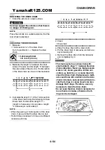
1. Measure:
• 15-link section “a” of the drive chain
Out of specification
→
Replace the drive
chain.
▼▼▼
▼
▼
▼▼▼
▼
▼
▼▼▼
▼
▼
▼▼▼
▼
▼
▼▼▼
▼
▼
▼▼▼
▼
▼▼▼
a. Measure the length “a” between the inner
sides of the pins and the length “b” between
the outer sides of the pins on a 15-link section
of the drive chain as shown in the illustration.
b. Calculate the length “c” of the 15-link section
of the drive chain using the following formula.
Drive chain 15-link section length “c” =
(length “a” between pin inner sides + length
“b” between pin outer sides)/2
NOTE:
• When measuring a 15-link section of the drive
chain, make sure that the drive chain is taut.
• Perform this procedure 2–3 times, at a different
location each time.
▲▲▲
▲
▲
▲▲▲
▲
▲
▲▲▲
▲
▲
▲▲▲
▲
▲
▲▲▲
▲
▲
▲▲▲
▲
▲▲▲
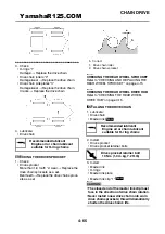
2. Clean:
• Drive chain
▼▼▼
▼
▼
▼▼▼
▼
▼
▼▼▼
▼
▼
▼▼▼
▼
▼
▼▼▼
▼
▼
▼▼▼
▼
▼▼▼
a. Wipe the drive chain with a clean cloth.
b. Put the drive chain in kerosene and remove
any remaining dirt.
c. Remove the drive chain from the kerosene
and completely dry it.
CAUTION:
ECA14290
• This motorcycle has a drive chain with
small rubber O-rings “1” between the drive
chain side plates. Never use high-pressure
water or air, steam, gasoline, certain sol-
vents (e.g., benzine), or a coarse brush to
clean the drive chain. High-pressure meth-
ods could force dirt or water into the drive
chain’s internals, and solvents will deterio-
rate the O-rings. A coarse brush can also
damage the O-rings. Therefore, use only
kerosene to clean the drive chain.
• Do not soak the drive chain in kerosene for
more than ten minutes, otherwise the O-
rings can be damaged.
15-link length limit
191.5 mm (7.54 in)
YamahaR125.COM
Содержание YZF-R125
Страница 1: ...5D7 F8197 E0 YAMAHAR125 COM SERVICE MANUAL YZF R125 ...
Страница 6: ...YamahaR125 COM ...
Страница 8: ...YamahaR125 COM ...
Страница 50: ...LUBRICATION SYSTEM CHART AND DIAGRAMS 2 27 EAS20410 LUBRICATION DIAGRAMS A 1 2 3 4 5 6 7 YamahaR125 COM ...
Страница 52: ...LUBRICATION SYSTEM CHART AND DIAGRAMS 2 29 1 2 3 4 YamahaR125 COM ...
Страница 53: ...LUBRICATION SYSTEM CHART AND DIAGRAMS 2 30 1 Camshaft 2 Crankshaft 3 Main axle 4 Drive axle YamahaR125 COM ...
Страница 54: ...COOLING SYSTEM DIAGRAMS 2 31 EAS20420 COOLING SYSTEM DIAGRAMS 1 2 3 4 5 6 2 4 8 7 2 5 6 9 YamahaR125 COM ...
Страница 60: ...CABLE ROUTING 2 37 A A A B B C C D D E E A C C D E E D B B A 1 1 1 1 1 2 2 2 3 3 3 4 4 4 5 5 YamahaR125 COM ...
Страница 70: ...CABLE ROUTING 2 47 YamahaR125 COM ...
Страница 73: ...YamahaR125 COM ...
Страница 102: ...ELECTRICAL SYSTEM 3 29 YamahaR125 COM ...
Страница 105: ...YamahaR125 COM ...
Страница 172: ...CHAIN DRIVE 4 67 YamahaR125 COM ...
Страница 181: ...ENGINE REMOVAL 5 6 2 2 4 1 3 YamahaR125 COM ...
Страница 263: ...THROTTLE BODY 7 8 YamahaR125 COM ...
Страница 264: ...AIR INDUCTION SYSTEM 7 9 EAS27040 AIR INDUCTION SYSTEM 1 2 3 YamahaR125 COM ...
Страница 268: ...AIR INDUCTION SYSTEM 7 13 YamahaR125 COM ...
Страница 271: ...YamahaR125 COM ...
Страница 283: ...CHARGING SYSTEM 8 12 1 AC magneto 3 Rectifier regulator 4 Main fuse 9 Battery YamahaR125 COM ...
Страница 285: ...CHARGING SYSTEM 8 14 YamahaR125 COM ...
Страница 295: ...SIGNALING SYSTEM 8 24 YamahaR125 COM ...
Страница 299: ...COOLING SYSTEM 8 28 YamahaR125 COM ...
Страница 323: ...FUEL INJECTION SYSTEM 8 52 YamahaR125 COM ...
Страница 327: ...FUEL PUMP SYSTEM 8 56 YamahaR125 COM ...
Страница 353: ...YamahaR125 COM ...
Страница 354: ...YamahaR125 COM ...


