ELECTRICAL COMPONENTS
8-66
EASB29B353
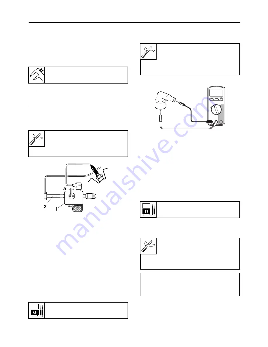
CHECKING THE IGNITION SPARK GAP
1. Check:
• Ignition spark gap
Out of specification
Perform the ignition
system troubleshooting, starting with step 4.
Refer to “TROUBLESHOOTING” on page 8-
3.
TIP
If the ignition spark gap is within specification,
the ignition system circuit is operating normally.
▼▼▼▼▼▼▼▼▼▼▼▼▼▼▼▼▼▼▼▼▼▼▼▼▼▼▼▼▼▼▼▼
a. Remove the spark plug cap from the spark
plug.
b. Connect the ignition checker “1” as shown.
c. Push the engine stop switch.
d. Measure the ignition spark gap “a”.
e. Crank the engine by pushing the start switch
and gradually increase the spark gap until a
misfire occurs.
▲▲▲▲▲▲▲▲▲▲▲▲▲▲▲▲▲▲▲▲▲▲▲▲▲▲▲▲▲▲▲▲
EASB29B354
CHECKING THE SPARK PLUG CAP
1. Remove:
• Spark plug cap
(from the spark plug lead)
2. Check:
• Spark plug cap resistance
Out of specification
Replace.
▼▼▼▼▼▼▼▼▼▼▼▼▼▼▼▼▼▼▼▼▼▼▼▼▼▼▼▼▼▼▼▼
a. Connect the digital circuit tester (
) to the
spark plug cap.
b. Measure the spark plug cap resistance.
▲▲▲▲▲▲▲▲▲▲▲▲▲▲▲▲▲▲▲▲▲▲▲▲▲▲▲▲▲▲▲▲
EASB29B355
CHECKING THE IGNITION COIL
1. Disconnect:
• Ignition coil terminal
(from the sub wire harness)
• Spark plug cap
(from the ignition coil)
2. Check:
• Primary coil resistance
Out of specification
Replace.
▼▼▼▼▼▼▼▼▼▼▼▼▼▼▼▼▼▼▼▼▼▼▼▼▼▼▼▼▼▼▼▼
a. Connect the digital circuit tester (
) to the ig-
nition coil.
Minimum ignition spark gap
6.0 mm (0.24 in)
Ignition checker
90890-06754
Oppama pet–4000 spark checker
YM-34487
2. Spark plug cap
Resistance
7.50–12.50 k
Digital circuit tester (CD732)
90890-03243
Model 88 Multimeter with
tachometer
YU-A1927
Primary coil resistance
2.16–2.64
Digital circuit tester (CD732)
90890-03243
Model 88 Multimeter with
tachometer
YU-A1927
• Positive tester probe
Ignition coil terminal 1 “1”
• Negative tester probe
Ignition coil terminal 2 “2”
Содержание YZ 2018 Series
Страница 6: ...EASB916006 YAMAHA MOTOR CORPORATION U S A YZ MOTORCYCLE LIMITED WARRANTY...
Страница 10: ......
Страница 40: ...MOTORCYCLE CARE AND STORAGE 1 28...
Страница 51: ...ELECTRICAL SPECIFICATIONS 2 10 Fuse s Main fuse 15 0 A Spare fuse 15 0 A Radiator fan motor fuse 5 0 A...
Страница 64: ...LUBRICATION SYSTEM CHART AND DIAGRAMS 2 23...
Страница 66: ...LUBRICATION SYSTEM CHART AND DIAGRAMS 2 25...
Страница 67: ...LUBRICATION SYSTEM CHART AND DIAGRAMS 2 26 1 Exhaust camshaft 2 Intake camshaft 3 Oil filter element 4 Oil pump...
Страница 68: ...LUBRICATION SYSTEM CHART AND DIAGRAMS 2 27...
Страница 69: ...LUBRICATION SYSTEM CHART AND DIAGRAMS 2 28 1 Camshaft 2 Oil pressure check bolt 3 Oil filter element 4 Oil pump...
Страница 70: ...CABLE ROUTING DIAGRAM 2 29 EASB29B065 CABLE ROUTING DIAGRAM...
Страница 72: ...CABLE ROUTING DIAGRAM 2 31...
Страница 74: ...CABLE ROUTING DIAGRAM 2 33...
Страница 76: ...CABLE ROUTING DIAGRAM 2 35...
Страница 78: ...CABLE ROUTING DIAGRAM 2 37...
Страница 80: ...CABLE ROUTING DIAGRAM 2 39...
Страница 82: ...CABLE ROUTING DIAGRAM 2 41...
Страница 84: ...CABLE ROUTING DIAGRAM 2 43...
Страница 235: ...ELECTRIC STARTER 5 38 5 Install Bolt 1 O ring 2 TIP Apply the lithium soap based grease on the O ring New...
Страница 255: ...OIL PUMP AND BALANCER GEAR 5 58 a 2 10 b 2 9 1 b 5 3 a 4 10 5 9 3 E c d 6 7 8 8 b 6...
Страница 276: ...TRANSMISSION 5 79...
Страница 290: ...FUEL TANK 7 5 A Left B Right 1 1 A 0 mm 0 in B 1 1 15 mm 0 59 in...
Страница 296: ...THROTTLE BODY 7 11...
Страница 299: ......
Страница 313: ...CHARGING SYSTEM 8 14...
Страница 321: ...COOLING SYSTEM For JPN 8 22...
Страница 351: ...FUEL PUMP SYSTEM 8 52 EASB29B345...
Страница 352: ...ELECTRICAL COMPONENTS 8 53 ELECTRICAL COMPONENTS EASB29B346 9 10 11 1 3 2 4 5 6 7 8...
Страница 354: ...ELECTRICAL COMPONENTS 8 55 11 10 9 2 3 1 6 7 8 4 5...
Страница 356: ...ELECTRICAL COMPONENTS 8 57 EASB29B347 CHECKING THE SWITCHES 4 1 3 2 B B Sb B B B B B B B B...
Страница 357: ...ELECTRICAL COMPONENTS 8 58 1 Engine stop switch 2 Neutral switch 3 Clutch switch 4 Start switch...
Страница 372: ...ELECTRICAL COMPONENTS 8 73 c Measure the fuel injector resistance...


