FUEL INJECTION SYSTEM
8-27
EASB29B340
YAMAHA DIAGNOSTIC TOOL
This model uses the Yamaha diagnostic tool to identify malfunctions.
For information about using the Yamaha diagnostic tool, refer to the operation manual that is included
with the tool.
FEATURES OF THE YAMAHA DIAGNOSTIC TOOL
A diagnosis can be made more quickly than traditional methods with the Yamaha diagnostic tool.
Using this software, ECU and sensor data, as well as fault diagnosis, vehicle maintenance, and any
necessary information can be recorded and displayed on your computer screen through a USB
adapter connected to the computer interface with a communication cable connected to the vehicle’s
ECU.
Data obtained in various functions can be saved as vehicle history, and can be accumulated.
FUNCTIONS OF THE YAMAHA DIAGNOSTIC TOOL
However, the diagnostic tool cannot be used to freely change the basic vehicle functions, such as
adjusting the ignition timing.
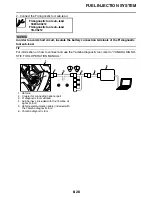
CONNECTING THE YAMAHA DIAGNOSTIC TOOL
1. Remove the coupler for connecting setting tool.
Yamaha diagnostic tool USB (US)
90890-03257
Yamaha diagnostic tool (A/I)
90890-03254
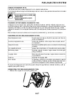
Fault diagnosis mode
Fault codes recorded on the ECU are read, and the con-
tents are displayed.
Function diagnostic mode
Check the operation of the output value of each sensor
and actuator.
Inspection mode
Determine whether each sensor or actuator is functioning
properly.
CO adjustment mode
Adjust the concentration of CO admissions during idling.
Monitoring mode
Displays a graph of sensor output values for actual oper-
ating conditions.
Logging mode
Records and saves the sensor output value in actual driv-
ing conditions.
View log
Displays the logging data.
ECU rewrite
If necessary, the ECU is rewritten using the ECU rewrite
data provided by Yamaha. Ignition timing adjustment, etc.
cannot be changed from the vehicle’s original state.
Содержание YZ 2018 Series
Страница 6: ...EASB916006 YAMAHA MOTOR CORPORATION U S A YZ MOTORCYCLE LIMITED WARRANTY...
Страница 10: ......
Страница 40: ...MOTORCYCLE CARE AND STORAGE 1 28...
Страница 51: ...ELECTRICAL SPECIFICATIONS 2 10 Fuse s Main fuse 15 0 A Spare fuse 15 0 A Radiator fan motor fuse 5 0 A...
Страница 64: ...LUBRICATION SYSTEM CHART AND DIAGRAMS 2 23...
Страница 66: ...LUBRICATION SYSTEM CHART AND DIAGRAMS 2 25...
Страница 67: ...LUBRICATION SYSTEM CHART AND DIAGRAMS 2 26 1 Exhaust camshaft 2 Intake camshaft 3 Oil filter element 4 Oil pump...
Страница 68: ...LUBRICATION SYSTEM CHART AND DIAGRAMS 2 27...
Страница 69: ...LUBRICATION SYSTEM CHART AND DIAGRAMS 2 28 1 Camshaft 2 Oil pressure check bolt 3 Oil filter element 4 Oil pump...
Страница 70: ...CABLE ROUTING DIAGRAM 2 29 EASB29B065 CABLE ROUTING DIAGRAM...
Страница 72: ...CABLE ROUTING DIAGRAM 2 31...
Страница 74: ...CABLE ROUTING DIAGRAM 2 33...
Страница 76: ...CABLE ROUTING DIAGRAM 2 35...
Страница 78: ...CABLE ROUTING DIAGRAM 2 37...
Страница 80: ...CABLE ROUTING DIAGRAM 2 39...
Страница 82: ...CABLE ROUTING DIAGRAM 2 41...
Страница 84: ...CABLE ROUTING DIAGRAM 2 43...
Страница 235: ...ELECTRIC STARTER 5 38 5 Install Bolt 1 O ring 2 TIP Apply the lithium soap based grease on the O ring New...
Страница 255: ...OIL PUMP AND BALANCER GEAR 5 58 a 2 10 b 2 9 1 b 5 3 a 4 10 5 9 3 E c d 6 7 8 8 b 6...
Страница 276: ...TRANSMISSION 5 79...
Страница 290: ...FUEL TANK 7 5 A Left B Right 1 1 A 0 mm 0 in B 1 1 15 mm 0 59 in...
Страница 296: ...THROTTLE BODY 7 11...
Страница 299: ......
Страница 313: ...CHARGING SYSTEM 8 14...
Страница 321: ...COOLING SYSTEM For JPN 8 22...
Страница 351: ...FUEL PUMP SYSTEM 8 52 EASB29B345...
Страница 352: ...ELECTRICAL COMPONENTS 8 53 ELECTRICAL COMPONENTS EASB29B346 9 10 11 1 3 2 4 5 6 7 8...
Страница 354: ...ELECTRICAL COMPONENTS 8 55 11 10 9 2 3 1 6 7 8 4 5...
Страница 356: ...ELECTRICAL COMPONENTS 8 57 EASB29B347 CHECKING THE SWITCHES 4 1 3 2 B B Sb B B B B B B B B...
Страница 357: ...ELECTRICAL COMPONENTS 8 58 1 Engine stop switch 2 Neutral switch 3 Clutch switch 4 Start switch...
Страница 372: ...ELECTRICAL COMPONENTS 8 73 c Measure the fuel injector resistance...


