background image

E-

12

ADVANCED YAMAHA ACTIVE SERVO TECHNOLOGY

The theory of Yamaha Active Servo Technology has been
based upon two major factors, the Helmholtz resonator and
negative-impedance drive. Active Servo Processing
speakers reproduce the bass frequencies through an “air
woofer”, which is a port or opening in the speaker’s cabinet.
This opening is used instead of, and performs the functions
of, a woofer in a conventionally designed speaker system.
Thus, signals of low amplitude within the cabinet can,
according to the Helmholtz resonance theory, be outputted
from this opening as waves of great amplitude if the size of
the opening and the volume of the cabinet are in the correct
proportion to satisfy a certain ratio.
In order to accomplish this, moreover, the amplitudes within
the cabinet must be both precise and of sufficient power
because these amplitudes must overcome the “load”
presented by the air that exists within the cabinet.

Thus it is this problem that is resolved through the
employment of a new design in which the amplifier supplies
special signals. If the electrical resistance of the voice coil
could be reduced to zero, the movement of the speaker unit
would become linear with respect to signal voltage. To
accomplish this, a special negative-impedance output-drive
amplifier for subtracting output impedance of the amplifier is
used.

By employing negative-impedance drive circuits, the
amplifier is able to generate precise, low-amplitude, low-
frequency waves with superior damping characteristics.
These waves are then radiated from the cabinet opening as
high-amplitude signals. The system can, therefore, by
employing the negative-impedance output drive amplifier
and a speaker cabinet with the Helmholtz resonator,
reproduce an extremely wide range of frequencies with
amazing sound quality and less distortion.
The features described above, then, are combined to be the
fundamental structure of the conventional Yamaha Active
Servo Technology.

Our new Active Servo Technology — Advanced Yamaha
Active Servo Technology — adopted Advanced Negative
Impedance Converter (ANIC) circuits, which allows the
conventional negative impedance converter to dynamically
vary in order to select an optimum value for speaker
impedance variation. With this new ANIC circuits, Advanced
Yamaha Active Servo Technology can provide more stable
performance and improved sound pressure compared with
the conventional Yamaha Active Servo Technology, resulting
in more natural and dynamic bass reproduction.

High-amplitude
bass sound

Cabinet

Port

Air woofer
(Helmholtz resonator)

Active Servo
Processing
Amplifier

Signals

Signals of low amplitude

Advanced Negative-
impedance Converter

Содержание YST-SW800

Страница 1: ...I YST SW800 Active Servo Processing Subwoofer System Caisson de grave avec asservissement actif OWNER S MANUAL MODE D EMPLOI U C A...

Страница 2: ...be connected to a power supply only of the type described in the operating instructions or as marked on the unit 11 Power Cord Protection Power supply cords should be routed so that they are not like...

Страница 3: ...le level of assurance that your use of this product in a residential environment will not result in harmful interference with other electronic devices This equipment generates uses radio frequencies a...

Страница 4: ...IV Nonskid pads Patins anti d rapages UNPACKING After unpacking check that the following item is contained DEBALLAGE Apr s le d ballage v rifier que la pi ce suivante est incluse...

Страница 5: ...falls or drops by the air pressure it may cause damage to the unit and or personal injury Never put a hand or a foreign object into the YST port located on the right side of this unit When moving thi...

Страница 6: ...s sound Refer to page 12 for details on Advanced YAMAHA Active Servo Technology This super bass sound adds a more realistic theater in the home effect to your stereo system This subwoofer can be easil...

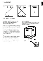
Страница 7: ...m it and the sound reflected by the wall may cancel out each other To prevent this from happening face the subwoofer system at an angle as in fig or Note There may be a case that you cannot obtain eno...

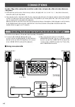
Страница 8: ...er Basically connect the subwoofer to the line output pin jack terminal s of the amplifier Refer to pages 4 and 5 for details If your amplifier does not have any line output terminal connect the subwo...

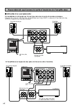
Страница 9: ...minals of the amplifier make sure that the amplifier has at least two sets of PRE OUT terminals If the amplifier has only one set of PRE OUT terminals do not connect the subwoofer to the PRE OUT termi...

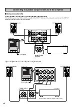
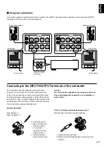
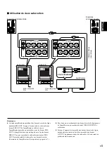
Страница 10: ...peaker output terminals of the amplifier m Using one subwoofer If your amplifier has only one set of main speaker output terminals Connect the speaker output terminals of the amplifier to the INPUT1 t...

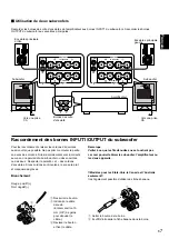
Страница 11: ...e speaker cords as short as possible Do not bundle or roll up the excess part of the cords If the connections are faulty no sound will be heard from the subwoofer or the speakers or both of them Make...

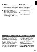
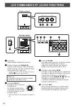
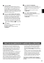
Страница 12: ...sts the high frequency cut off point Frequencies higher than the frequency selected by this control are all cut off and no output One graduation of this control represents 10 Hz 4 VOLUME control Adjus...

Страница 13: ...s is about 100 Hz This function is available only when the power of the subwoofer is on by setting the STANDBY ON button to ON 7 PHASE switch Normally this switch is to be set to the REV reverse posit...

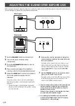
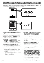
Страница 14: ...e more bass effect than when this unit is not used If the desired response cannot be obtained adjust the HIGH CUT control and the VOLUME control again 7 Set the PHASE switch to the position which give...

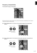
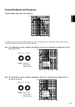
Страница 15: ...res below show the optimum adjustment of each control and the frequency characteristics when this subwoofer is combined with a typical main speaker system PHASE Set to the REV reverse position VOLUME0...

Страница 16: ...is a special negative impedance output drive amplifier for subtracting output impedance of the amplifier is used By employing negative impedance drive circuits the amplifier is able to generate precis...

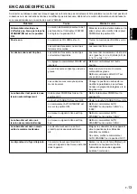
Страница 17: ...way from such appliances and or reposition the connected speaker cables Otherwise set the AUTO STANDBY switch to the OFF position Turn down the volume on the amplifier etc connected to this unit or cu...

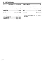
Страница 18: ...Response 18 Hz 160 Hz 10 dB Power Supply USA and Canada models AC 120V 60 Hz U K and Europe models AC 230V 50 Hz Australia model AC 240V 50 Hz Power Consumption 250W Dimensions W x H x D 390 mm x 482...

Страница 19: ...Lors du d placement de cet appareil ne pas le tenir par le port cela peut entra ner des blessures et ou endommager l appareil Le disjoncteur du foyer peut disjoncter de mani re inattendue lorsqu un si...

Страница 20: ...e qui concerne Advanced YAMAHA Active Servo Technology se reporter la page 12 Ces basses fr quences ajoutent un effet r aliste cin matographique aux sons fournis par une cha ne st r o Ce subwoofer peu...

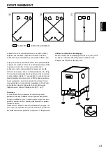
Страница 21: ...n mis par l enceinte et le son renvoy par le mur s annuleront mutuellement Pour viter ce probl me placer le subwoofer angle oblique par rapport au mur comme indiqu sur la fig ou Remarque Les sons de t...

Страница 22: ...a aux borne s de sortie de ligne prise broche de l amplificateur Pour plus de d tails se reporter aux pages 4 et 5 Si l amplificateur n est pas quip d une borne de sortie de ligne raccorder le subwoof...

Страница 23: ...ateur veiller ce que l amplificateur poss de au moins deux jeux de bornes PRE OUT Si l amplificateur ne poss de qu un seul jeu de bornes PRE OUT ne pas raccorder le subwoofer aux bornes PRE OUT Raccor...

Страница 24: ...eul subwoofer Si l amplificateur n est quip que d un seul jeu de bornes de sortie d enceintes principales Raccorder les bornes de sortie d enceintes de l amplificateur aux bornes INPUT1 du subwoofer e...

Страница 25: ...uge positif Noir n gatif 1 Desserrer le bouton 2 Introduire le c ble d nud Enlever environ 10 mm 3 8 de ga ne pour d nuder le c ble 3 Revisser le bouton et fixer le c ble Remarque Veiller ce que les f...

Страница 26: ...haute fr quence Les fr quences sup rieures au niveau r gl sur cette commande sont toutes annul es et ne sont donc pas mises Chaque graduation de cette commande correspond 10 Hz 4 Commande VOLUME Pour...

Страница 27: ...te fonction est utilisable seulement lorsque le subwoofer est sous tension la touche STANDBY ON sur ON 7 Commutateur PHASE Ordinairement ce commutateur doit se trouver en position REV phase invers e C...

Страница 28: ...effet de basse que lorsque cet appareil n est pas utilis Si la r ponse souhait e ne peut pas tre obtenue r gler nouveau la commande HIGH CUT et la commande VOLUME 7 R gler le commutateur PHASE sur la...

Страница 29: ...montrent le r glage optimal de chaque commande et les caract ristiques des fr quences lorsque ce subwoofer est associ des enceintes principales classiques PHASE Mettre sur la position REV phase inver...

Страница 30: ...t tre simul gr ce un circuit d attaque imp dance n gative qui soustrait l imp dance de l enceinte de l imp dance de sortie de l amplificateur Le circuit d attaque imp dance n gative d livre de fa on p...

Страница 31: ...limentation sur la prise secteur et ou mettre l interrupteur POWER sur la position ON Tourner la commande VOLUME vers la droite Les raccorder fermement Les raccorder correctement c est dire de L gauch...

Страница 32: ...caract ristiques techniques sont modifiables sans pr avis YAMAHA ELECTRONICS CORPORATION USA 6660 ORANGETHORPE AVE BUENA PARK CALIF 90620 U S A YAMAHA CANADA MUSIC LTD 135 MILNER AVE SCARBOROUGH ONTAR...

Отзывы: