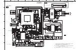
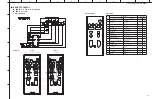
Yamaha YAS-207 Скачать руководство пользователя страница 39

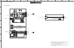
  Components having special characteristics are marked 

 and must be replaced 

with parts having specifications equal to those originally installed.

  Schematic diagram is subject to change without notice.

● ⚠印のある部品は、安全性確保部品を示しています。部品の交換が必要な場合、

パーツリストに記載されている部品を使用してください。

● 本回路図は標準回路図です。改良のため予告なく変更することがあります。

[2/4]

[2/4]

[2/4]

[2/4]

[2/4]

[2/4,3/4]

[2/4]

[2/4]

[4/4]

[2/4,3/4]

[2/4]

[2/4]

[2/4]

[2/4]

[4/4]

[2/4,3/4]

[2/4,3/4]

[2/4]

[4/4]

[2/4]

[2/4]

[2/4]

[2/4]

[2/4]

[2/4]

[2/4]

[2/4,3/4]

[2/4,3/4]

[4/4]

[2/4]

[2/4]

[4/4]

[4/4]

[2/4]

[2/4]

[2/4]

[2/4]

[2/4]

[4/4]

BT_3.3V

MCU_3.3V

HDMII_5V_ON/OFF

CSRA67175_1.05V

CSRA67175_3.3V

YSS952_1.8V

BACKUP EEPROM

MAIN MCU

OPTION

* R162

NC

others

J

VERSION

47K

0R

G, B

3.3V

LED_VCC

TO BT MODULE

TO LED  BOARD

MCU UPDATE 

TO DSP

TO AMPLIFIER

RST

DET.

SDA

SCL

GND

GND

MGLB3216M161T5R0-LF

MGLB3216M161T5R0-LF

A/A

0R

NC

YAS

ATS

VERSION

* R133

YAS-207 CENTER UNIT_MCU SECTION

Fsw=580KHz

Fsw=580KHz

GND

GND

R144

1K

R145

100K

C134

1nF

C135

1nF

C140

0.1uF

C141

1nF

C139

10uF

FB119

600R

C132

1nF

C133

10uF

C136

1uF

R148

100R

1

VOUT

2

VSS

3

VIN

IC107

LN61C

1

2

3

4

5

6

7

8

9

10

CN100

FFC-1.0mm_V

R171

100R

C142

0.1uF

C103

0.1uF

C102

10uF

C101

0.1uF

R103

100K

R104

10K

R105

10K

R106

10K

R107

100R

C108

1nF

Q100

NCE2305

Q101

2N3904

C100

10uF

1 VIN

2

GND

3

EN

4

NC

5

VOUT

IC100
BL9198-33BAPRN

R100

100K

C110

0.1uF

C109

10uF

C107

0.1uF

C106

10uF

C105

0.1uF

C104

10uF

1 VIN

2

GND

3

EN

4

NC

5

VOUT

IC101
BL9198-33BAPRN

R102

1K

C119

NC

C120

0.1uF

C121

47uF

R114

33.2K1%

C118

0.1uF

C117

47uF

C113

NC

C116

0.1uF

C114

47uF

R109

3.74K1%

R110

10K1%

C112

0.1uF

C111

47uF

R108

10K

R112

10K

R101
100K

R111

100K

R153

4.7K

R152

4.7K

FB108
600R

FB105

160R

FB103

160R

FB102

600R

FB110

600R

FB121

600R

R165

470R

R113

10K1%

R121

47K

FB101

600R

C143
47pF

R140

1K

R159

0R

R158

0R

R157

100R

R156

0R

R155

0R

R115

NC

FB107
600R

FB109

NC

R139

1K

FB111
NC

C145

1uF

C125

NC

C124

NC

C123

NC

C122

NC

1 VIN

2

GND

3

EN

4

NC

5

VOUT

IC104
NC

R146

NC

R162

*

L100

2.2uH1.85A

NR3015-2R2NC

D100

RB160

EC100

470u16V

R132

100K

R151

10K

D101

1SS355

R134

10K1%

C131

0.1uF

EC101

47u16V

R143

1K

R154

1K

R131

10K1%

R116

0R

R130

0R

R129

0R

R128

0R

R127

0R

R118

4.7K

R117

4.7K

C128

NC

C129

47pF

C130

47pF

C127

NC

RST

DET

GNDB

VCC

3V3

SDA

SCL

FB104
600R

FB106

600R

C115

22uF

PRI

AC_DET

C126

10nF

R123

1K

R124

1K

R125

NC

R126

1K

R149

100R

Y100

16MHz

C138

18pF

C137

18pF

R164

100R

1 A0

2 A1
3 A2
4 GND

5

SDA

6

SCL

7

WP

8

VCC

IC105

BL24C02

R160

1K

C144

100pF

C146

1uF

R168

100R

R167

100R

R166

100R

R170

100R

+5VA

DGND

R147

100K

AMP_SDZ

AMP_FAULTZ

AMP_MUTE

R163
100K

Q102

NCE2305

Q103

RTN144C

FB113

600R

L101
3.3uH1.4A

NR3015-3R3NC

D102

ESD

1

P60/SCL0

2

P61/SDA0

3

P62/EXSCL0

4

P63

5

P33/TI51/TO51/INTP4

6

P75

7

P74

8

P73/KR3

9

P72/KR2

10

P71/KR1

11

P70/KR0

12

P32/INTP3/OCD1B

36

P140/PCL/INTP6

35

P00/TI000

34

P01/TI010/TO00

33

P130

32

ANI0/P20

31

ANI1/P21

30

ANI2/P22

29

ANI3/P23

28

ANI4/P24

27

ANI5/P25

26

ANI6/P26

25

ANI7/P27

37 P120/INTP0/EXLVI

38

P41

39

P40

40

RESET

41

P124/XT2/EXCLKS

42

P123/XT1

43

FLMDO

44

P122/X2/EXCLK/OCD0B

45

P121/X1/OCD0A

46

REGC

47

VSS

48

VDD

24

AVSS

23

AVREF

22

P10/SCK10/TXD0

21

P11/SI10/RXD0

20

P12/SO10

19

P13/TXD6

18

P14/RXD6

17

P15/TOH0

16

P16/TOH1/INTP5

15

P17/TI50/TO50

14

P30/INTP1

13

P31/INTP2OCD1A

IC106

UPD78F0514A

R174

10K1%

1

GND

2

SW

3

VIN

4

VFB

5

EN

6

VBST

IC102

TPS562201DDCR

C147
0.1uF

R172
0R

1

GND

2

SW

3

VIN

4

VFB

5

EN

6

VBST

IC103

TPS562201DDCR

R173
0R

C148
0.1uF

R176

NC

R175

100K

C149

1nF

C150

1nF

R177

100K

R150

10K

R120

10K

RP100

1K*4

D103

RB160

1

OUT

2

GND

3

VCC

IC108

HM338-S3

C152

0.1uF

C151

10uF

C153

100pF

OUT

G

VCC1

R137

10K

R136

100R

R135

22R

FB120
600R

R179

1K

R184

NC

R185

10K

VBUS_EN

R186

10R

R187

*

NTC

R133

*

SYSTEM_RST

BT_TX

BT_RX

MAPX_3.3V

VCC3.3V

MCU_3V3

HDMI+5V

BT_3.3V

MAPX_1.05V

BT_ON/OFF

HDMI_ON/OFF

MAMP_FAULTZ

HDMI_RESET

YSS952_1V8

YSS952_3.3V

BT_RESET

WAKE_UP_BT

AC_DET

HDMI_MUTE

HDMI_INTB

FLASH_ERR

PRI

BT_VREG

MCU-3V3

FLMD0

MCU-RX

MCU-RESET

SCL

SDA

HDMI_SCL

HDMI_SDA

AMP_MUTE

EXCLK

DGND

RESET

+5V_IN

DGND

DGND

MAMP_SDZ

MCU-TX

KEY_SCL

KEY_SDA

DGND

DGND

DGND

DGND

DGND

DGND

DGND

DGND

DGND

DGND

DGND

DGND

DGND

DGND

DGND

DGND

DGND

DGND

DGND

DGND

DGND

DGND

DGND

DGND

DGND

DGND

DGND

KEY_RST

KEY_SCL

KEY_SDA

KEY_RST

KEY_3V3

VBUS_EN

POWER_ON/OFF

DGND

Remote control

sensors

to SUB (LED)_CN600

Page 43

B2

YAS-CU207

ATS-CU2070

A

B

C

D

E

F

G

H

I

J

1

2

3

4

5

6

7

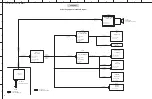
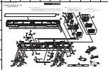
YAS-CU207/ATS-CU2070/NS-WSW42

39

MAIN 1/4

 CIRCUIT DIAGRAMS

FOR INFORMATION ONLY (COMPONENT PARTS NOT AVAILABLE)

Содержание YAS-207

Страница 1: ...ive components Discharge any static electricity your body may have accumulated by grounding yourself to the ground buss in the unit heavy gauge black wires connect to this buss IMPORTANT Turn the unit...

Страница 2: ...ypes for the repair work Sn Ag Cu tin silver copper Sn Cu tin copper Sn Zn Bi tin zinc bismuth Caution As the melting point temperature of the lead free solder is about 30 C to 40 C 50 F to 70 F highe...

Страница 3: ...er reverse the battery polarities when installing Do not short the batteries Do not attempt to recharge these batteries Do not disassemble the batteries Never heat batteries or throw them into fire AD...

Страница 4: ...N The YAS 207 ATS 2070 consists of the YAS CU207 ATS CU2070 and NS WSW42 YAS 207 YAS CU207 NS WSW42 YAS CU207 NS WSW42 ATS CU2070 NS WSW42 YAS 207 ATS 2070 4 YAS CU207 ATS CU2070 NS WSW42 YAS CU207 AT...

Страница 5: ...YAS CU207 ATS CU2070 ATS CU2070 YAS CU207 J model U C T K A B G V models Top view Front view Bottom view Rear view J model U C T K A B G V models Labels 5 YAS CU207 ATS CU2070 NS WSW42 YAS CU207 ATS C...

Страница 6: ...U C models A model B model T model G model K model Labels YAS CU207 6 YAS CU207 ATS CU2070 NS WSW42 YAS CU207 ATS CU2070 NS WSW42...

Страница 7: ...V model J model B model U model G model A model ATS CU2070 7 YAS CU207 ATS CU2070 NS WSW42 YAS CU207 ATS CU2070 NS WSW42...

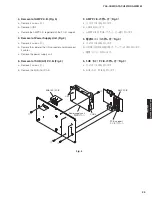
Страница 8: ...Top view Rear view NS WSW42 8 YAS CU207 ATS CU2070 NS WSW42 YAS CU207 ATS CU2070 NS WSW42...

Страница 9: ...U C models T model K model A model Rear view 9 YAS CU207 ATS CU2070 NS WSW42 YAS CU207 ATS CU2070 NS WSW42...

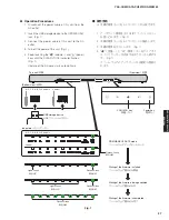
Страница 10: ...B model G model V model J model 10 YAS CU207 ATS CU2070 NS WSW42 YAS CU207 ATS CU2070 NS WSW42...

Страница 11: ...REMOTE CONTROL PANELS FSR78 U C T K A B G V models FSR77 J model 11 YAS CU207 ATS CU2070 NS WSW42 YAS CU207 ATS CU2070 NS WSW42...

Страница 12: ...el AC 230 V 50 Hz G model YAS CU207 AC 110 240 V 50 60 Hz ATS CU2070 AC 220 240 V 50 Hz V model AC 110 V 60 Hz J model AC 100 V 50 60 Hz Power Consumption 30 W Standby Power Consumption HDMI CEC stand...

Страница 13: ...anadian model T Chinese model K Korean model A Australian model B British model G European model V Taiwan model J Japanese model The Bluetooth word mark and logos are registered trademarks owned by Bl...

Страница 14: ...930 36 5 8 457 18 27 1 290 11 3 8 279 11 4 1 8 min 20 3 4 7 9 1 4 3 8 4 6 1 8 1 4 60 2 3 8 58 5 2 1 4 1 5 1 16 108 4 1 4 Mounting hole size 5 mm 1 4 10 Side view Top view Front view Rear view DIMENSI...

Страница 15: ...IVER FULL RANGE FRONT L R DRIVER TWEETER SUB LED P C B SUB AC P C B SUB JACK P C B 1 2 3 4 5 6 7 8 7 8 5 6 2 3 1 4 4 5 4 4 Top view Rear view Front view DRIVER WOOFER AMP P C B POWER SUPPLY UNIT 1 2 3...

Страница 16: ...BTL connected the ground side of the measuring instrument to be connected to the speaker terminal MUST be kept in floating condition NS WSW42 NS WSW42 YAS CU207 Operation check NS WSW42 NS WSW42 does...

Страница 17: ...loth for protection of this unit against any damage and place this unit on cloth with its bottom cabinet assembly facing up b Remove 16 screws c Remove the bottom cabinet assembly AC 1 Ass y Fig 1 a A...

Страница 18: ...2 2 Removal of Driver Tweeter Fig 2 The driver removal procedure is the same for both right and left a Remove 2 screws b Remove the solder of the connector and disconnect the cable c Remove the solde...

Страница 19: ...a Remove 2 screws b Remove CN402 b Remove the SUB USB P C B 2 3 SUB JACK P C B Fig 3 a 2 b CN200 b SUB JACK P C B 2 4 SUB USB P C B Fig 3 a 2 b CN402 b SUB USB P C B Rubber sheet and the cloth SUB USB...

Страница 20: ...ove 4 screws b Remove the solder of the L N connector and disconnect 2 cables c Remove the power supply unit 2 5 MAIN P C B Fig 4 a 6 b CN100 CON2 c MAIN P C B 2 6 Fig 4 a 4 b L N 2 c Rubber sheet and...

Страница 21: ...moval of SUB LED P C B Fig 5 a Remove the SUB LED P C B 2 7 SUB AC P C B Fig 5 a 2 b SUB AC P C B 2 8 SUB LED P C B Fig 5 a SUB LED P C B Cover SUB AC P C B SUB LED P C B Bottom cabinet assembly Ass y...

Страница 22: ...front frame assembly by pushing it up gradually using the metalblade or the like Notes Removing the side frame front panel assembly with the flatblade screwdriver only without using the metalblade or...

Страница 23: ...river subwoofer b Disconnect the connector connected to the terminal of the driver subwoofer c Remove the driver subwoofer 2 Fig 2 a 6 b c Ruber sheet and the cloth Connectors Cabinet assembly Ass y D...

Страница 24: ...r Panel Assembly Fig 3 a Remove 6 screws Screws are identified with arrow marks b Remove the rear panel assembly Fig 3 Ruber sheet and the cloth Cabinet Rear panel assembly Ass y 24 YAS CU207 ATS CU20...

Страница 25: ...gether with the P C B support 5 Removal of Power Supply Unit Fig 4 a Remove 4 screws b Remove the solder of the L N connector and disconnect 2 cables c Remove the power supply unit 6 Removal of SUB AC...

Страница 26: ...his unit to the AC outlet and turn off the power Then while touching the volume key touch the power key and all indicators will flash and initialization will be completed AC Required Tools USB storage...

Страница 27: ...ashes Fig 1 Update of the firmware starts automatically AC 1 USB Fig 1 2 AC 3 Fig 1 4 Fig 1 This unit Front view J model U C T K A B G V models Indicators U C T K A B G V models J model Bottom view FI...

Страница 28: ...rom the AC outlet and perform the firmware updating procedure again from the beginning AC List of error display Display of indicator ANALOG SURROUND BASS EXTENSION CLEAR VOICE Factor DD DTS DPL HDMI T...

Страница 29: ...ction works to turn off the power even if it is turned on Touch the power key again to turn on the power and the DD DTS indicator indicates the causal factor of the protection function Protection Disp...

Страница 30: ...MEMO 30 YAS CU207 ATS CU2070 NS WSW42 YAS CU207 ATS CU2070 NS WSW42...

Страница 31: ...aster_1 I2C_Master_2 GPIO IR IN RST GPIO 78F0514A MCU GPIOs 3 3V 1 05V 3 3V I2C DAC_OUT 3 6 CSRA67175DA01 MAPX DSP GPIO_BT_Control I2C_Slave_1 I2S_IN3 S PDIF_IN4 SPI UART Line_in_L R I2S_IN2 S PDIF_IN...

Страница 32: ...ENSOR DC 0 7 8V LN61C RESET DC 1 8 3 6V MFI337 2 0C APPLE AUTH DC 2 4 5 5V HKRX178LDA W OPTIC RECEIVER OUTPUT CURRENT HDMI Repeater DSP PC 0 5W Ityp 9 04mA Imax 10 85mA Imax 653 6mA Ityp 508 8mA S1 EN...

Страница 33: ...T I2S B3V3 OP AMP DIO2032 IN AP AN OPAMP 5V TO EEPROM FAULT PB5 MCU TO BL9198 33 LDO 3 3V BL9198 33 LDO 3 3V CSRA65700 TO GPIOs PRI DET DAC PC5 RED GREEN PD4 PD6 M3V3 B3V3 50 60Hz RST Y801 2402MHz 248...

Страница 34: ...mA Imax 4 5mA INPUT VOLTAGE 2 ohms Pmax 100W Ptyp 30W 1 3 power Ityp 1 619A Imax 5 326A 100V 240V 50 60Hz OUTPUT CURRENT DIO2032 OP AMP DC 2 5 5 5V Ityp 6mA Imax 9mA Imax 5 3A Ityp 1 6A PC 0 4W CSRA65...

Страница 35: ...nter Unit MCU BT Receiver AMP SMPS P C B AC INLET DC OUT AC IN DC IN BT Receiver SUBWOOFER Subwoofer SUBWOOFER Unit UPGRADE USB MAIN SUB JACK SUB LED SUB USB AMP SUB AC SUB AC CN600 CN200 CN401 CN400...

Страница 36: ...l sensors Writing port YAS CU207 ATS CU2070 A B C D E F G H I J 1 2 3 4 5 6 7 36 YAS CU207 ATS CU2070 NS WSW42 PRINTED CIRCUIT BOARDS FOR INFORMATION ONLY COMPONENT PARTS NOT AVAILABLE Note Precaution...

Страница 37: ...E ONLY CLEAR VOICE SUB Side A LED SUB Side B LED SUB Side B AC SUB Side A AC SUB Side B USB SUB Side A USB SUB Side B JACK SUB Side A JACK ANALOG TV Power supply unit AC IN MAIN CN402 MAIN CN200 YAS C...

Страница 38: ...de B Power supply unit DRIVER SUBWOOFER PAIRING Writing port STANDBY indicator indicator SUB Side B AC SUB Side A AC Power supply unit AC IN NS WSW42 A B C D E F G H I J 1 2 3 4 5 6 7 38 YAS CU207 ATS...

Страница 39: ...VCC 3V3 SDA SCL FB104 600R FB106 600R C115 22uF PRI AC_DET C126 10nF R123 1K R124 1K R125 NC R126 1K R149 100R Y100 16MHz C138 18pF C137 18pF R164 100R 1 A0 2 A1 3 A2 4 GND 5 SDA 6 SCL 7 WP 8 VCC IC1...

Страница 40: ...36 GND 37 VBAT_SENSE 38 GND 39 VBAT 40 CHG_EXT 41 VBUS 42 GND 43 1V8_SMPS 44 VREG_EN 45 VDD_PADS 46 GND 47 MIC_RN 48 MIC_RP 49 MIC_BIASB 50 MIC_LN 51 MIC_LP 52 MIC_BIASA 53 SPK_LN 54 SPK_LP 55 SPK_RP...

Страница 41: ...303 PESDR0524P5L NC 2 I2 3 GND 5 I4 10 O1 4 I3 1 I1 6 O4 7 O3 9 O2 8 GND D302 PESDR0524P5L NC 2 I2 3 GND 5 I4 10 O1 4 I3 1 I1 6 O4 7 O3 9 O2 8 GND D305 PESDR0524P5L NC 2 I2 3 GND 5 I4 10 O1 4 I3 1 I1...

Страница 42: ...AM0 16 SYNC 17 AVCC 18 PVCC 19 PVCC 20 BSNL 21 OUTNL 22 GND 23 OUTPL 24 BSPL 25 GND 26 BSNR 27 OUTNR 28 GND 29 OUTPR 30 BSPR 31 PVCC 32 PVCC 33 EPAD 34 EPAD IC401 TPA3116D2DADR R406 NC R423 NC R420 1K...

Страница 43: ...TVS R624 NM R625 NM R626 NM LED610 LED601 C616 1nF C615 1nF C607 1nF C608 1nF G3 VCC1 3V3 SCL1 SDA1 RST1 DET C621 1nF LED607 C619 1nF LED606 C618 1nF LED605 C617 1nF LED604 C614 1nF LED603 C613 1nF FB...

Страница 44: ...0 1uF C603 4 7uF D600 TVS C610 470pF C611 470pF C601 NC S T R TS RS CN602 AUX JACK FB601 600R FB600 600R D603 TVS 1 2 3 4 5 6 CN603 SAN 6P_H R635 100R R636 0R R637 1K R638 1K R639 47K R640 47K FB603 6...

Страница 45: ...30pF C874 220nF C875 220nF C876 220nF C877 220nF EC801 470UF 35V C878 1nF C863 1nF C864 1nF C879 1nF C846 0 1uF C847 0 1uF F801 1A 63V 1 VIN 2 GND 3 EN 4 NC 5 VOUT IC807 BL9198 33BAPRN C849 0 1uF C853...

Страница 46: ...sed at each location of this unit are not supplied individually sponge 700 x 25 x 2 and EVA packing 130 x 8 x 1 are included in the SERVICE TOOLS list These are the only sizes available as service par...

Страница 47: ...0 N02942 030X0 UABG 12 ZZ069800 NON SKID PAD 11x11x2 360 010229 000X0 13 ZZ069300 BOTTOM COVER SHEET 20 4 17 5x19x0 5 354 000210 000X0 14 ZZ069100 SCREW 3x10 372 P30100 BTNX1 15 ZW790900 SCREW 3x14 37...

Страница 48: ...F 380 N02945 000XN 314 ZZ061000 SIDE FRAME ASSEMBLY with FABRIC G31 YS207A 050X0 315 ZZ061500 FRONT FRAME ASSEMBLY with FABRIC BADGE G31 YS207B 050X0 316 ZZ061600 DUCT 300 N02948 000XN 317 ZZ061300 SC...

Страница 49: ...HDMI 78 4A 3 TV TV 78 DF 4 ANALOG 78 D1 5 BLUETOOTH BLUETOOTH 78 29 6 SURROUND 78 B4 7 STEREO 78 50 8 CLEAR VOICE 78 5C 9 BASS EXTENSION 78 8B 10 BLUETOOTH STANDBY BLUETOOTH 78 34 11 DIMMER 78 BA 12 S...

Страница 50: ...nds Once the center unit and subwoofer have been paired and indicator a wireless connection established the will glow and the center unit and subwoofer turn on If the indicator on the subwoofer does n...

Отзывы: