background image

Содержание T-80

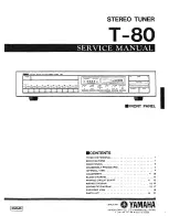
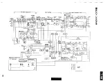
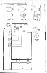
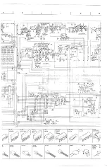
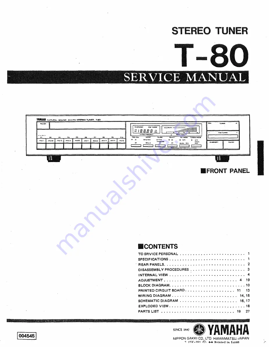
Страница 1: ...CATlONS 1 REARPANELS 2 DISASSEMBLY PROCEDURES 3 INTERNALVIEW 4 ADJUSTMENT 4 19 BLOCKDIAGRAM 10 PRINTED ClRGUlT BOARD 11 13 WIRING DIAGRAM 14 15 SCHEMATIC DIAGRAM 16 17 EXPLODED VIEW 18 PARTS LIST 19 27 NIPPON GAKKl CO LTD HAMAMATSU JAPAN 1 I W q Q l Printpd in laoan ...

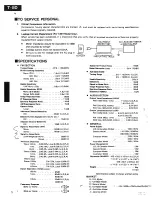
Страница 2: ...rtion Mono 100Hz DX0 03 Local 0 02 U C R A 1kHz DX0 15 Local 0 03 U C R A 6kHz DX0 4 Local 0 06 U C R A Stereo lM3Hz DX0 5 Local 0 04 U C R A 1kHz DXO 5 Local 0 03 U C R A 6kHz DX0 8 Local 0 07 IU C R AI 4OkHz Dev Stereo 100Hz DX 0 5 Local 0 05 E lkHz DX 0 5 Local 0 04 El 6 3kHz OX 0 5 Local 0 08 E Strreo Separation IkHz Local mkHz a 65dB 1kHz 65dB U C R A 60dB E 10kHz 50dB U C R A 40dB E F affiy ...

Страница 3: ...WREAR PANELS U S CANADIAN MODEL EUROPEAN MODEL GENERAL MODEL AUSTRALIAN MODEL ...

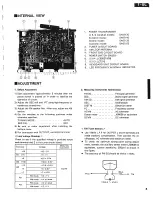
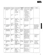
Страница 4: ...CCAL OFF 5 Be sure to make adjustment after installing the bottom cover 6 For connection with OUT PUT use HIGH terminal Line Voltage Checkup Check to see if the specified voltage is provided across each terminal and E in the tuner circuit board 2 Measuring Instruments Abbreviation FM SG FM signal generator SSG Stereo signal generator AM SG AM signal generator OSC Oscilloscope DlST M Distortion met...

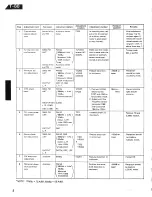
Страница 5: ...nter meter posi tioned at zero center R197 and J150 to force stereo mode 2 Adjust until the frequency across 5 98MHz lkHz aural distortion is LOCAL mode PLL input phase adjustment 12 l1501 19K C169 300 2 FM ANT OUTPUT FC terminals C169 and E becomes 19kHz i lOHz FM S G Stereo L R modulation OSC lncrease output to maximum Remove FC and 2 2M52 resistor ...

Страница 6: ...hannel alone adjust OUTPUT Lch VR103 until output is increased level to minimum 9 modulation 98MHz lkHz open across itivity is deterio d with FM ATT 98MHz lkHz 10kHz output differs between when the FM NR switch is at ON and OFF position ...

Страница 7: ... con Ifirmation l i TUNING MODE SW AUTO Digital Control Section AM ANT AM SG 630kHz r 0 1 kHz 1440kHz 0 1kMz 1080kHz 0 1kHz 400Hz 30 modu lation switches and con indicator above the PRESET ed respectively In the same way store the AM The TUNING MODE LED turns manuallmono MODE switch to operation con be made with the TUNING button for UP and DOWN oper ations Also confirm that when FM i s re ceived ...

Страница 8: ...the POWER switch is ON MODE switch to turned on the frequency in P1 INITlAL STATION is displayed without respect to the frequency which is displayed before the POWER switch is turned off Therefore before turning off the P W E R switch display a frequency which has After 5 or more t this time confirm that the seconds have pass frequency in P1 is displayedand ed turn on the ...

Страница 9: ...TUNER CIRCUIT BOARD I Connect resistor across R467 to 5268 Full scallesignal level indicator 1 Separation adiustrnent 1 ladiustment Center Meter Ji 00036 or equivalent m ...

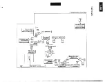
Страница 10: ...7 F M FRONT END SECTION DC NFB MPX DECODER SECTION ...

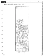
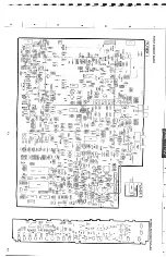
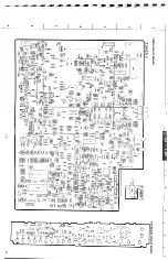
Страница 11: ...CIRCUIT BOARD Panern Side FRONT END CIRCUIT BOARD ...

Страница 12: ......

Страница 13: ......

Страница 14: ......

Страница 15: ......

Страница 16: ......

Страница 17: ......

Страница 18: ......

Страница 19: ......

Страница 20: ......

Отзывы: