background image

Troubleshooting

85

SREV1—Owner’s Manual

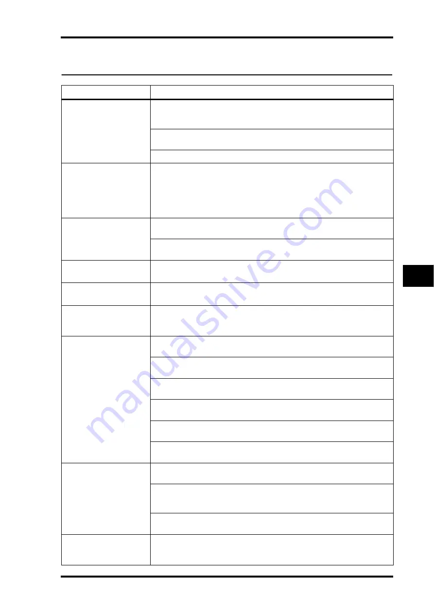
Troubleshooting

Symptom

Advice

Cannot turn on the 
SREV1.

Make sure that the power cord is connected properly to a suitable AC wall outlet 
and the SREV1. See “Connecting the Power Cord” on page 26 for more informa-
tion.

Make sure that the SREV1 POWER switch is set to ON. See “Turning On & Off the 
SREV1” on page 26 for more information.

If you still cannot turn on the SREV1, contact your Yamaha dealer.

The POWER indicator 
lights up when the SREV1 
is turned on, but the 
INPUT and OUTPUT 
indicators flash 
alternately.

Contact your Yamaha dealer.

Cannot turn on the 
RC-SREV1.

Make sure that the remote cable is connected between the SREV1 and RC-SREV1 
properly. See “Connecting the RC-SREV1 Remote Controller” on page 22.

Make sure that the RC-SREV1 POWER switch is in the ON position. See “Turning 
On & Off the RC-SREV1” on page 26 for more information.

The FS LOCK indicators 
flash alternately.

The SREV1 is locked but not synchronized to the external wordclock source. See 
“Selecting the Wordclock Source” on page 75 for more information.

The FS LOCK indicators 
flash together.

The SREV1 is neither locked nor synchronized to the external wordclock source. 
See “Selecting the Wordclock Source” on page 75 for more information.

The FS status section of 
the RC-SREV1 display 
shows “UNLOCK”.

The SREV1 is neither locked nor synchronized to the external wordclock source. 
See “Selecting the Wordclock Source” on page 75 for more information.

Connected an input 
signal but there’s no 
output.

If you’re using slot inputs, make sure the I/O cards are installed properly and 
secured using the thumbscrews. See “Installing I/O Cards” on page 84.

Make sure the input is assigned to the proper channel. See “Assigning Inputs” on 
page 35 for more information.

Use the level meters to help trace the signal. See “Metering” on page 37 for 
more information.

Check the channel’s input and output level settings. See “Setting Input & Output 
Levels” on page 36 for more information.

Is the Bypass mode is set to REV-MUTE, the reverb balance set to 100%, and the 
reverb level set to –

?

Are you connected to the correct outputs? See “Output Assignments” on page 9 
for more information.

Can’t hear any reverb.

Is the SREV1 bypassed. See “Bypassing the SREV1” on page 40 for more informa-
tion.

Make sure that the Reverb Balance parameter is not set to 0%. See “Main 2 
Parameters”
 on page 54 and “Fine Reverb Parameters” on page 56 for more 
information.

Make sure that the Reverb Level parameter is not set to 0 dB. See “Fine Reverb 
Parameters” on page 56 for more information.

Recalled a program but 
only its title is displayed, 
no program number.

Probably because the program was recalled from a drive. Program numbers 
(P01–P12) are displayed only when programs are recalled from the Quick memo-
ries. See “RC-SREV1 Display” on page 18 for more information.

Содержание S Rev1

Страница 1: ...E Keep This Manual For Future Reference SAMPLING REVERBERATOR Owner s Manual MEMORY CARD CD ROM POWER ON OFF INPUT OUTPUT CLIP SIGNAL 1 2 1 2 3 CH 4 3 4 48K 44 1K FS LOCK ...

Страница 2: ...THIS MAINS LEAD ARE COLOURED IN ACCORDANCE WITH THE FOLLOWING CODE GREEN AND YELLOW EARTH BLUE NEUTRAL BROWN LIVE As the colours of the wires in the mains lead of this apparatus may not correspond with the coloured markings identifying the terminals in your plug proceed as follows The wire which is coloured GREEN and YELLOW must be connected to the terminal in the plug which is marked by the lette...

Страница 3: ...f the power cord is damaged e g cut or a bare wire is exposed ask your dealer for a replacement Using the unit with a damaged power cord is a fire and electrical shock hazard Do not plug several pieces of equipment into the same AC outlet This may overload the AC outlet and could be a fire or electrical shock hazard It may also affect the per formance of some equipment If you notice any abnormalit...

Страница 4: ...ean the unit Use only a soft dry cloth If the unit is stored in a cold place e g overnight in a car and then moved to a warmer environment or if the temperature rises sharply condensation may form inside the unit which may affect performance In this case the unit should be allowed to acclima tize for about one hour before use When the wordclock is changed on the wordclock master device noise may o...

Страница 5: ...cally designed for writing on CDs and write only on the designated area Do not attach a label to a disc If a disc is stored in a cold place e g overnight in a car and then moved to a warmer environment or if the temperature rises sharply condensation may form on the disc surface which may affect performance In this case the disc should be allowed to accli matize for about one hour before use Do no...

Страница 6: ... Pentium are registered trade marks and MMX is a trademark of Intel Corporation PCMCIA is a registered trade mark of the Personal Computer Memory Card International Association Tascam Digital Interface is a trademark and Tascam and Teac are registered trademarks of Teac Corporation Windows is a trademark of Microsoft Corporation Yamaha is a trade mark of Yamaha Corporation All other trademarks are...

Страница 7: ...he flow of air from the two cooling fans Do not mount the SREV1 above equipment that produces a lot of heat such as a power amplifier Conventions Used in this Manual In this manual the SREV1 Sampling Reverberator the optional RC SREV1 Remote Controller and the SREV1 software are referred to as the SREV1 RC SREV1 and SREV1 software respectively The RC SREV1 features two types of button physical but...

Страница 8: ... Music Nederland Service Afdeiing Kanaalweg 18 G 3526 KL UTRECHT Tel 030 2828425 Gooi de batterij niet weg maar lever hem in als KCA This apparatus contains a lithium battery for memory back up For the removal of the battery at the moment of the disposal at the end of the service life please consult your retailer or Yamaha Service Center as follows Yamaha Music Nederland Service Center Address Kan...

Страница 9: ...C SREV1 26 Using an Optional RC SREV1 AC Adapter 27 Adjusting the RC SREV1 Brightness Contrast 27 Using CD ROMs 28 Using PC Cards 29 4 Basic Operation 31 SREV1 Startup 32 RC SREV1 Startup 32 About the Internal Operations at Startup 33 Selecting Reverb Modes 34 Assigning Inputs 35 Setting Input Output Levels 36 Metering 37 Setting the Meter Mode 39 Using Peak Hold 39 Bypassing the SREV1 40 Setting ...

Страница 10: ...eters to Control Changes 71 8 Wordclocks 73 Wordclocks the SREV1 74 Wordclock Connections 74 Selecting the Wordclock Source 75 Wordclock Hookup Examples 78 9 I O Options 81 I O Options the SREV1 82 Available I O Cards 82 Choosing I O Cards 83 Installing I O Cards 84 Troubleshooting 85 Appendix 87 Error Messages 87 Confirmation Messages 88 General Messages 89 General Specifications 90 Digital Input...

Страница 11: ...Welcome 1 SREV1 Owner s Manual Welcome 1 In this chapter Welcome to the SREV1 2 The SREV1 in a Nutshell 2 SREV1 Features 4 SREV1 Basics 6 SREV1 Block Diagram 10 ...

Страница 12: ...tic characteristics onto any audio signal In addition to stereo reverb 2 channel mode the SREV1 offers four channel process ing for surround reverb 4 channel mode Alternatively the SREV1 can be configured as two fully independent reverberators 2 channel x2 mode each with its own inputs outputs and program settings Thirty two of Yamaha s new convolution chips provide the necessary horsepower for re...

Страница 13: ...be set simultaneously Fine parameter editing adds pre convolution 4 band PEQ post convolution 4 band PEQ and impulse response data loading Reverb parameters can be edited individually or grouped Reverb balance and reverb level parameters for each channel can be controlled individually via MIDI Control Changes Two AES EBU inputs and outputs providing 4 channels are built in and two mini YGDAI Yamah...

Страница 14: ...s Programs combine impulse response data with variable parameters such as reverb time initial delay EQ and more Quick memories hold six instantly recallable programs 2 channel or 4 channel mode 12 programs 2 channel x2 mode Quick memory programs can be recalled via MIDI Projects provide a convenient way to manage programs for each job Programs and projects can be saved on the Internal Card or PC C...

Страница 15: ...nd Tascam Optional RC SREV1 Remote Controller Control up to four SREV1s Large 320 x 240 dot display with fluorescent backlight and adjustable brightness and contrast Four motorized faders data wheel and INC DEC buttons for parameter editing Input and output signal clip indicators Power supplied by the SREV1 DC IN connector for use with optional AC adapter and custom remote cables Others Yamaha CD ...

Страница 16: ... time it takes the reverb to decay to 60 dB and more convolution is required to provide reverberation to 90 dB or 120 dB so the convolution time must be between 1 5 and 2 times more than the reverb time Impulse Response Data Impulse response data contains the impulse response information i e acoustic char acteristics of a measured environment Preset programs come with their own impulse response da...

Страница 17: ...roject and come back to it at any time Projects can be saved to the Internal Card or PC Card where they can be write protected There are three types of project 2 channel 4 channel and 2 channel x2 Each project type is available only when the corresponding mode is selected You can t for example select a 2 channel project in 4 channel mode Projects are managed on the Project pages See Working with P...

Страница 18: ... 45 for more information The following diagram shows how programs and projects can be transferred to and from the drives and Quick memories and impulse response data transferred from the drives P01 P02 P03 P04 P06 PC ATA CARD FLASH CARD P05 Drives CD ROM PC Card Internal Card Current program Impulse response data Project Quick memories See the Library pages for program and drive save load operatio...

Страница 19: ...g reverb mode wordclock source I O select I O level and MIDI settings are not stored within each program but they are stored in the SREV1 s battery backed memory Output Assignments The following table shows the fixed output assignments for each mode File Extension File Type TM4 Impulse response data Yamaha original format TMC Compressed and encrypted impulse response data Yamaha original format SP...

Страница 20: ... EQ Post EQ Bypass Rev Mute On Off SLOT 2 SLOT 1 AES EBU IN 2 AES EBU IN 1 SLOT 2 SLOT 1 Input Select AES EBU OUT 2 Output Meter As above Right Front right A right Left Front left A left As above Rear left B left As above Rear right B right Bypass Direct Out On Off Reverb Level Reverb Balance Output Level Convo lution ...

Страница 21: ...ring the SREV1 RC SREV1 11 SREV1 Owner s Manual Touring the SREV1 RC SREV1 2 In this chapter SREV1 Front Panel 12 SREV1 Rear Panel 14 RC SREV1 Control Surface 16 RC SREV1 Display 18 RC SREV1 Rear Panel 20 ...

Страница 22: ...1 kHz and whether or not the SREV1 is locked to the selected wordclock source See Selecting the Wordclock Source on page 75 for more information D POWER switch indicator This switch is used to turn on the power to the SREV1 The POWER indicator lights up when the SREV1 is turned on See Turning On Off the SREV1 on page 26 for more information E MEMORY CARD slot PC Cards can be inserted here for load...

Страница 23: ...ee Using CD ROMs on page 28 for more information J CD ROM eject button This button is used to eject CD ROMs See Using CD ROMs on page 28 for more information K Emergency disc eject hole This hole is used to manually eject CD ROMs that cannot be ejected in the normal way Use a pin like tool of 2 mm or less in diameter insert it into the hole and push gently A straightened paper clip makes an ideal ...

Страница 24: ...he AC outlet is grounded then the SREV1 will be grounded sufficiently through the power cord If the AC outlet does not provide a suitable ground however a ground connection should be made to this grounding screw Grounding is also an effective method for eliminating hum interference and other noise E DIGITAL OUT AES EBU connectors These two XLR 3 32 type connectors AES1 and AES2 transmit up to four...

Страница 25: ...tion H SERIAL 1 2 ports These 8 pin mini DIN connectors are used to connect up to four SREV1s in a multi ple unit system See Multiple SREV1s on page 63 for more information I REMOTE port This 9 pin D sub connector is used to connect the RC SREV1 See Connecting the RC SREV1 Remote Controller on page 22 for more information J WORD CLOCK IN connector This BNC connector can be used to receive an exter...

Страница 26: ...the SREV1 on page 40 for more information C PROGRAM button This button selects the Program Library and Project pages D PARAMETER MAIN button This button selects the Main 1 and Main 2 pages E PARAMETER FINE button This button selects the Rev Pre EQ and Post EQ pages F UTILITY button This button selects the Setup DIO Meter I O and MIDI pages 1 DEC 1 INC PARAMETER CURSOR ENTER UTILITY PROGRAM BYPASS ...

Страница 27: ... buttons work in parallel with the DATA wheel and are used for selecting pro grams or projects and setting parameter values Use the 1 DEC button to decrease a value the 1 INC button to increase it K DATA wheel Thiswheelisusedforselectingprogramsorprojectsandsettingparametervalues Turn it clockwise to increase a value counterclockwise to decrease it L Cursor buttons These buttons are used to maneuv...

Страница 28: ...unction appears here ON SREV1 bypassed or OFF See Bypassing the SREV1 on page 40 for more information FS status The SREV1 sampling rate is displayed here 48 kHz or 44 1 kHz and whether or not it s locked to the selected wordclock source LOCK or UNLOCK See Selecting the Wordclock Source on page 75 for more information Selected SREV1 This is the SREV1 currently selected for control from the RC SREV1...

Страница 29: ...each fader appears along the bottom of the display For pages selected with the PARAMETER MAIN button the names of the parameters assigned to the faders appear and for pages selected with the PARAMETER FINE button the channel names appear as shown below Parameter Channel ...

Страница 30: ...e optionalAC adapter s cable in order to prevent accidental disconnection See Using an Optional RC SREV1 AC Adapter on page 27 for more information D REMOTE port This 9 pin D sub connector is used to connect the RC SREV1 to the SREV1 with the remote cable supplied with the RC SREV1 See Connecting the RC SREV1 Remote Controller on page 22 for more information E BRIGHT control This control is used t...

Страница 31: ...Steps 22 Connecting the RC SREV1 Remote Controller 22 Hookup Examples 23 Connecting the Power Cord 26 Turning On Off the SREV1 26 Turning On Off the RC SREV1 26 Using an Optional RC SREV1 AC Adapter 27 Adjusting the RC SREV1 Brightness Contrast 27 Using CD ROMs 28 Using PC Cards 29 ...

Страница 32: ...the Power Cord on page 26 and Turning On Off the SREV1 on page 26 6 Turn on the RC SREV1 and Adjust the brightness and contrast See Turning On Off the RC SREV1 on page 26 and Adjusting the RC SREV1 Brightness Contrast on page 27 The SREV1 is now ready for use Connecting the RC SREV1 Remote Controller The RC SREV1 should be connected to the SREV1 using the supplied 9 pin D sub remote cable as shown...

Страница 33: ... channel x2 mode AC IN SLOT 1 SLOT 2 WORD CLOCK IN REMOTE 2 OUT IN MIDI SERIAL 1 DIGITAL AES EBU IN OUT 3 1 2 2 3 1 1 2 1 2 2 3 1 3 1 2 1 DEC 1 INC PARAMETER CURSOR ENTER UTILITY PROGRAM BYPASS PARAMETER FINE PARAMETER MAIN INPUT CLIP OUTPUT CLIP CH 1 2 3 4 REMOTE AES EBU AES EBU 1 1 DIGITAL RECORDING CONSOLE RC SREV1 SREV1 SREV1 settings Reverb mode 2 channel Input assignment AES1 1 2 Wordclock s...

Страница 34: ...INC PARAMETER CURSOR ENTER UTILITY PROGRAM BYPASS PARAMETER FINE PARAMETER MAIN INPUT CLIP OUTPUT CLIP CH 1 2 3 4 RC SREV1 REMOTE AES EBU DIGITAL I O CARD MODEL MY8 AE AES EBU DIGITAL RECORDING CONSOLE SREV1 SREV1 settings Reverb mode 2 channel 4 channel or 2 channel x2 Input assignment SLOT1 1 8 Wordclock source MY8 AE 1 2 AES EBU card Alternatives MY8 AT ADAT format MY8 TD Tascam format MY8 AE c...

Страница 35: ...AC IN SLOT 1 SLOT 2 WORD CLOCK IN REMOTE 2 OUT IN MIDI SERIAL 1 DIGITAL AES EBU IN OUT 3 1 2 2 3 1 1 2 1 2 2 3 1 3 1 2 1 DEC 1 INC PARAMETER CURSOR ENTER UTILITY PROGRAM BYPASS PARAMETER FINE PARAMETER MAIN INPUT CLIP OUTPUT CLIP CH 1 2 3 4 SREV1 REMOTE ANALOG IN AD CARD MODEL MY4 AD 4 3 2 1 ANALOG OUT DA CARD MODEL MY4 DA 4 3 2 1 1 2 3 4 1 2 3 4 DIGITAL RECORDING CONSOLE RC SREV1 SREV1 settings R...

Страница 36: ...To turn on the RC SREV1 set its POWER switch to the ON position The startup screen appears and after communication is established between the SREV1 and RC SREV1 the Program page appears See RC SREV1 Startup on page 32 for more information 2 To turn off the RC SREV1 set its POWER switch to the OFF position The RC SREV1 receives its power from the SREV1 via the remote cable so if it doesn t come on ...

Страница 37: ...ctor on the rear of the RC SREV1 Loop the AC adapter cable around cable clip shown here to prevent accidental disconnection Adjusting the RC SREV1 Brightness Contrast Boththebrightnessandcontrastof theRC SREV1displaycan be adjusted to suit your working environment or personal preference 1 Use the CONT control to set the display contrast Contrast adjusts the balance between pixels that are on and t...

Страница 38: ...c tray appears pull it out 2 With the labeled side facing up carefully fit the disc onto the central spindle The disc sits flat when it s in correctly 3 Push the disc tray fully into the SREV1 to close it When a CD ROM is being read the activity indicator lights up The SREV1 takes between 20 and 30 seconds to recognize a CD ROM after it s inserted 4 To eject a CD ROM press the eject button 5 When ...

Страница 39: ...for use in a few seconds Although rare in some cases the PC Card may not be recognized If this happens try reinserting the card If it s not recognized after several tries contact yourYamaha dealer When a card is being written or read the activity indicator lights up Do not eject the card or turn off the power while this indicator is lit 2 To eject a card make sure that the activity indicator is no...

Страница 40: ...l Operations at Startup 33 Selecting Reverb Modes 34 Assigning Inputs 35 Setting Input Output Levels 36 Metering 37 Setting the Meter Mode 39 Using Peak Hold 39 Bypassing the SREV1 40 Setting the Bypass Mode 40 Using the Title Edit dialog Box 41 Working with Quick Memories 42 Working with the Library 45 Working with Projects 48 ...

Страница 41: ...to the RC SREV1 so long as the RC SREV1 POWER switch is set to the ON position the RC SREV1 will be turned on at the same time as the SREV1 is turned on and the RC SREV1 will startup normally If however you are using multiple SREV1s connected together using serial cables make sure that all SREV1s have completed startup before turning on the RC SREV1 When the RC SREV1 is turned on startup screen 1 ...

Страница 42: ... case be sure to insert the necessary PC Card or CD ROM before starting the SREV1 Although the SREV1 s battery backed memory stores the titles of the current and Quick memory programs it does not store the actual program or impulse response data so this must be loaded each time the SREV1 is started If a necessary PC Card or CD ROM is not inserted the message DATA FILE NOT FOUND INSERT PCMCIA CARD ...

Страница 43: ...he SREV1 switches to the selected Reverb mode the RC SREV1 displays the message SETTING REV MODE and the SREV1 INPUT and OUTPUT signal indi cators light up in sequence Once the mode has been set the mode title appears in the Reverb mode section of the display theProgrampageisselected andthecursorappearsatthesamepositionitdoes when the power is turned on The SREV1 switches to the selected mode the ...

Страница 44: ...f that slot are available 1 Use the UTILITY button to locate the DIO page 2 Use the cursor buttons to select the dots in the INPUT SELECT section of the page A dotted circle indicates that an input is assignable two dots indicate that an input is unavailable 3 Press the ENTER button to assign an input to a channel The input is assigned to the channel and the dotted circle changes to a solid dot 2 ...

Страница 45: ...vidually This section explains how to adjust input and output levels on the Meter I O page See page 54 for information on the Main 2 page 1 Use the UTILITY button to locate the Meter I O page 2 Use the cursor buttons to select the INPUT LEVEL and OUTPUT LEVEL param eters for each channel 3 Use the faders to set the levels The DATA wheel or 1 DEC and 1 INC buttons can also be used to set levels in ...

Страница 46: ... In 2 channel mode input and output signal levels can be metered simultaneously In 4 channel or 2 channel x2 mode however either the input or output levels can be metered not both simultaneously See Setting the Meter Mode on page 39 for more information The 14 segment LCD meters have the following resolution CLIP 3dB 6dB 9dB 12dB 15dB 18dB 24dB 30dB 36dB 42dB 48dB 54dB 60dB The following table sho...

Страница 47: ... for each channel can be metered by using the SIGNAL and CLIP indicators on the SREV1 front panel The SIGNAL indicators light up when the signal is 34 dB below clipping and are intended to show the presence of a signal while the CLIP indicators light up when the signal is actually clipping RC SREV1 CLIP indicators Input and output signal levels for each channel can be metered for clipping by using...

Страница 48: ...select the METER MODE button 3 Use the ENTER button to toggle between INPUT and OUTPUT mode The 14 segment meters are set accordingly Using Peak Hold By keeping the highest lit segment of each meter illuminated the Peak Hold function offers a convenient way to check for signal peaks In addition to the meters on the RC SREV1 display pages the Peak Hold function also works with the dedicated CLIP in...

Страница 49: ...output signals are still affected by the Reverb Balance and Reverb Level parameters 1 Use the UTILITY button to locate the Meter I O page 2 Use the cursor buttons to select the BYPASS MODE button 3 Use the ENTER button to toggle between DIRECT OUT and REV MUTE The Bypass mode is set accordingly Bypass BYPASS Button Display SREV1 Off Normal operation On Bypassed1 1 Depends on the Bypass mode Direct...

Страница 50: ...or buttons to select it and then press the ENTER but ton The selected character is inserted into the title at the cursor position and the cursor automatically moves one place to the right Use the SPC button to enter a space at the cursor position Use the INS button to insert a space at the cursor position and move the subsequent characters to the right Characters that are moved beyond the right ha...

Страница 51: ...an be recalled instantly The recalled program becomes the current program 1 Use the PROGRAM button to locate the Program page 2 Use the DATA wheel or the 1 DEC and 1 INC buttons to select a program from the list 3 Use the cursor buttons to select the RECALL button and then press ENTER If the current program contains unsaved changes a warning message appears Select YES to discard the changes and re...

Страница 52: ... then press ENTER The current program is stored to the selected Quick memory and the Edit status indi cator disappears see page 18 Editing Program Titles The titles of programs already stored in the Quick memories can be edited as follows 1 Use the PROGRAM button to locate the Program page 2 Use the DATA wheel or the 1 DEC and 1 INC buttons to select a pro gram The titles of write protected progra...

Страница 53: ...erwriting 1 Use the PROGRAM button to locate the Program page 2 Use the DATA wheel or the 1 DEC and 1 INC buttons to select a pro gram 3 Use the cursor buttons to select the PROTECT button and then press ENTER The Protect icon appears to the right of the program s title 4 Press the ENTER button again to unprotect the program The Protect icon disappears ...

Страница 54: ...loaded program becomes the current program The preset programs on the supplied CD ROM are loaded into the Internal Card at the factory 1 Use the PROGRAM button to locate the Library page 2 Use the cursor buttons to select a drive button and then press ENTER to make it the active drive The programs stored on the active drive appear in the program list 3 Use the DATA wheel or the 1 DEC and 1 INC but...

Страница 55: ...on and then press ENTER If a program with the same title already exists a confirmation dialog box appears Select YES to overwrite the existing program or select NO to cancel the operation Note that if the existing program is write protected it cannot be overwritten The current program and its impulse response data is saved to the selected drive and the Edit status indicator disappears see page 18 ...

Страница 56: ...s Deleting Library Programs Programs stored on the following drives can be deleted Internal Card or PC Card The preset programs loaded into the Internal Card at the factory are also available on the supplied CD ROM 1 Use the PROGRAM button to locate the Library page 2 Use the cursor buttons to select a drive button and then press ENTER to make it the active drive The programs stored on the active ...

Страница 57: ...e the PROGRAM button to locate the Project page 2 Use the cursor buttons to select a drive button and then press ENTER to make it the active drive The projects stored on the active drive appear in the project list 3 Use the DATA wheel or the 1 DEC and 1 INC buttons to select a project from the list 4 Use the cursor buttons to select the LOAD button and then press ENTER A confirmation message appea...

Страница 58: ...og box appears Select YES to overwrite the existing project or select NO to cancel the operation Note that if the existing project is write protected it cannot be overwritten The project is saved to the selected drive Editing Project Titles The titles of projects stored on the following drives can be edited Internal Card or PC Card 1 Use the PROGRAM button to locate the Project page 2 Use the curs...

Страница 59: ... the project s title 5 Press the ENTER button again to unprotect the project The Protect icon disappears Deleting Projects Projects stored on the following drives can be deleted Internal Card or PC Card 1 Use the PROGRAM button to locate the Project page 2 Use the cursor buttons to select a drive button and then press ENTER to make it the active drive The projects stored on the active drive appear...

Страница 60: ...Editing Programs 51 SREV1 Owner s Manual Editing Programs 5 In this chapter Main 1 Parameters 52 Main 2 Parameters 54 Fine Reverb Parameters 56 Pre EQ 57 Post EQ 59 Loading Impulse Response Data 61 ...

Страница 61: ...hoose which channel by using the buttons in the DISPLAY CHANNEL section of the page Below that section is the REV graph which displays the reverb parameter settings graphically and the PRE EQ graph which displays the Pre EQ settings graphically If the EQ is turned off on the Pre EQ page see page 57 the EQ graph appears shaded The Main 1 pages for each mode are shown below 1 Use the PARAMETER MAIN ...

Страница 62: ...ed by using the Initial Delay parameter Here the reverb time is 2 0 seconds initial delay is 200 ms exagger ated for illustration clarity and the reverb balance is 50 Parameter Range Steps Description REV TIME 0 3 1 1 Actual maximum reverb time depends on the impulse response data 0 1 sec Reverb time INITIAL DELAY 0 1 500 0 ms 0 1 ms Initial delay time LOW EQ 18 0 dB to 18 0 dB 0 1 dB Pre EQ low g...

Страница 63: ...DISPLAY CHANNEL section of the page Below that section is the REV graph which displays the reverb parameter settings graphically and the PRE EQ graph which displays the Pre EQ settings graphically If the EQ is turned off on the Pre EQ page see page 57 the EQ graph appears shaded Likewise if the HPF filter type parameter is set to THRU on the Pre EQ page that also appears shaded The Main 2 pages fo...

Страница 64: ...reverb and dry signals 0 all dry 100 all reverb INPUT LEVEL 72 0 dB to 6 0 dB 0 1 dB Input level OUTPUT LEVEL 72 0 dB to 6 0 dB 0 1 dB Output level HPF 16 0 Hz 23 6 kHz 1 12 oct Pre EQ HPF frequency Time Amplitude Direct signal Reverb time 2 0 sec Initial delay 0 1 ms Reverb balance 0 Direct signal reflections All reflections Time Amplitude Reverb time 2 0 sec Initial delay 0 1 ms Reverb balance 5...

Страница 65: ...sor buttons to select the REV TIME INITIAL DELAY REV BALANCE or REV LEVEL parameter 3 Use the faders DATA wheel or 1 DEC and 1 INC buttons to adjust the selected parameter Note that since adjustments to the REV TIME parameter do not take effect immedi ately there is a small delay between adjusting the reverb time by using for example a fader and the new reverb time being applied especially when ch...

Страница 66: ...not active when say the HIGH band is set to H SHELF The Pre EQ pages for each mode are shown below Note that the LOW band gain and HIGH band gain parameters can also be adjusted on the Main 1 page see page 52 Likewise the HPF frequency parameter can also be adjusted on the Main 2 page see page 54 On these pages however the channels are grouped 1 Use the PARAMETER FINE button to locate the Pre EQ p...

Страница 67: ...to THRU the HPF parameter on the Main 2 page is inac tive Parameter HPF LOW1 1 Can be used as a peaking EQ 10 0 10 or low shelving EQ L SHELF MID2 2 Peaking EQ HIGH3 3 Can be used as a peaking EQ 10 0 10 high shelving EQ H SHELF or low pass filter LPF Gain G 18 dB to 18 dB 0 1 dB steps Frequency F 16 0 Hz 23 6 kHz 1 12 oct steps Q 10 0 0 10 Filter Type T THRU4 HPF 4 The HPF is bypassed when set to...

Страница 68: ... addition to numeric values EQ settings are displayed graphically Inactive parameters appear shaded Q for example is not active when say the HIGH band is set to H SHELF The Post EQ pages for each mode are shown below 1 Use the PARAMETER FINE button to locate the Post EQ page Use the ON OFF button next to each EQ graph to turn on and off the Post EQ for each channel 2 Use the cursor buttons to sele...

Страница 69: ...ving EQ L SHELF or high pass filter HPF L MID2 2 Peaking EQ H MID3 3 Peaking EQ HIGH4 4 Can be used as a peaking EQ 10 0 10 high shelving EQ H SHELF or low pass filter LPF Gain G 18 dB to 18 dB 0 1 dB steps Frequency F 16 0 Hz 23 6 kHz 1 12 oct steps Q 10 0 0 10 Filter Type T PEAKING L SHELF HPF THRU5 5 The HPF and LPF are bypassed when set to THRU PEAKING PEAKING PEAKING H SHELF LPF THRU6 6 The H...

Страница 70: ... for each mode are shown below 1 Use the PARAMETER FINE button to locate the Rev page 2 Select the DATA LOAD button and then press ENTER The Data Load page appears 3 Use the cursor buttons to select a drive button and then press ENTER to make it the active drive The impulse response data stored on the active drive appear in the file list 4 Use the DATA wheel or the 1 DEC and 1 INC buttons to selec...

Страница 71: ...ter assigned to your PC Card while it s inserted in your PC The 2 channel SP2 and 4 channel SP4 programs that you create are stored in the yamaha srev prog folder and 2 channel 4 channel and 2 channel x2 projects are stored in the yamaha srev proj folder When you copy or move any of these files to another PC Card by using your PC be sure to use the same folder organization and naming otherwise the...

Страница 72: ...V1s 63 SREV1 Owner s Manual Multiple SREV1s 6 In this chapter About Multiple SREV1s 64 Connections 64 Multiple unit Operating Notes 65 Selecting SREV1s from the RC SREV1 65 Multiple unit Hookup with the RC SREV1 64 ...

Страница 73: ...atically assigned ID 1 and the other SREV1s are assigned IDs in order of connection as shown 2 SERIAL 1 SREV1 1 RC SREV1 SERIAL 1 SERIAL 2 REMOTE SREV1 2 SREV1 3 SERIAL 1 SERIAL 2 SREV1 4 SERIAL 1 SERIAL 2 MEMORY CARD CD ROM POWER ON OFF INPUT OUTPUT CLIP SIGNAL 1 2 1 2 3 CH 4 3 4 48K 44 1K FS LOCK MEMORY CARD CD ROM POWER ON OFF INPUT OUTPUT CLIP SIGNAL 1 2 1 2 3 CH 4 3 4 48K 44 1K FS LOCK MEMORY...

Страница 74: ... from the RC SREV1 1 Use the UTILITY button to locate the Setup page shown below 2 Use the cursor buttons to select the SREV 1 SREV 2 SREV 3 or SREV 4 button in the CONNECT section of the page The button of the currently selected SREV1 appears highlighted The buttons of uncon nected SREV1s appear shaded 3 Press the ENTER button A confirmation message appears 4 Select YES to continue or select NO t...

Страница 75: ...wner s Manual MIDI 7 In this chapter MIDI the SREV1 68 MIDI Ports 68 MIDI Pages 69 Setting the MIDI Receive Channels 69 Assigning Quick Memory Programs to Program Changes 70 Assigning Parameters to Control Changes 71 ...

Страница 76: ...each channel can be assigned to MIDI Control Changes and then controlled remotely from other MIDI equipment When a Control Change message is received the assigned parameter is controlled See Assigning Parameters to Control Changes on page 71 for more information The SREV1 can be set to receive Program Change and Control Change messages on any MIDI Channel from 1 through 16 and in 2 channel x2 mode...

Страница 77: ...DI page There are two MIDI Channel settings in 2 channel x2 mode one for A and one for B 1 Use the UTILITY button to locate the MIDI page 2 Use the cursor buttons to select the CH parameter in the MIDI RECEIVE CHAN NEL section of the page 3 Use the DATA wheel or 1 DEC and 1 INC buttons to select a MIDI Chan nel from 1 through 16 or OFF When OFF is selected the SREV1 ignores received MIDI messages ...

Страница 78: ...L LEVEL GAIN 13 14 15 16 PHONES MONITOR OUT OUT MONITOR 2TR IN 15 16 2TR IN 13 14 15 16 26dB 1 26dB 2 26dB 3 26dB 4 26dB 5 26dB 6 26dB 7 26dB 8 26dB 9 26dB 10 26dB 11 26dB 12 PAD DIGITAL MIXING CONSOLE L STEREO R CLIP 3 6 9 12 15 18 24 30 36 42 48 EQ SOLO 1 RETURN 2 PARAMETER HIGH SELECTED CHANNEL 1 RETURN 2 FUNCTION MEMORY HI MID LO MID LOW PAN F G PAN F G UTILITY MIDI SETUP VIEW EFFECT 1 EFFECT ...

Страница 79: ...der graph and parameter value select another page then select the previous page again The following illustration shows the type of MIDI equipment that can be used with the SREV1 for remote parameter control using Control Change messages PHANTOM 48V OFF ON PHANTOM 48V INPUT BAL 2TR PHONES L R IN LEVEL LEVEL GAIN 13 14 15 16 PHONES MONITOR OUT OUT MONITOR 2TR IN 15 16 2TR IN 13 14 15 16 26dB 1 26dB ...

Страница 80: ...Wordclocks 73 SREV1 Owner s Manual Wordclocks 8 In this chapter Wordclocks the SREV1 74 Wordclock Connections 74 Selecting the Wordclock Source 75 Wordclock Hookup Examples 78 ...

Страница 81: ...you must decide which device to use as the wordclock master and which devices to use as slaves The SREV1 can be used as a 48 kHz wordclock master or slaved to an external word clock source of 44 1 kHz or 48 kHz It can receive an external wordclock signal via an AES EBU input SLOT input or the BNC WORD CLOCK IN connector In a system where all devices share a common wordclock it s important that all...

Страница 82: ...ighted as shown here Note When the wordclock source is changed on the wordclock master device noise may occur from the SREV1 s outputs especially if an MY8 AT I O card is installed so turn down your power amps beforehand otherwise any connected speakers may be damaged Condition Source Description Always available INT 48K Internal 48 kHz wordclock default setting When lockable external wordclock pr...

Страница 83: ...source The following table outlines each step in the transition from wordclock unlock to lock If the external wordclock frequency is neither 44 1 kHz nor 48 kHz for example it s 32 kHz the transition from unlock to lock will stop at step 2 and the SREV1 outputs will remain muted Condition Wordclock Source Button FS LOCK Indicators RC SREV1 FS Status Indicator Internal wordclock Lock yes Sync yes E...

Страница 84: ...by using the SREV1 s FS LOCK indicator or the RC SREV1 s FS status indicator If a previously selected wordclock source is no longer available for example when an I O card is removed the wordclock source button appears shaded In this case select another wordclock source in order to use the SREV1 Step Condition Wordclock Source Button FS LOCK Indicators RC SREV1 FS Status Indicator Notes 1 Lock yes ...

Страница 85: ...ROJECT SEARCH RTN TO ZERO REW FF STOP PLAY REC ROLL BACK LAST REC SET DIGITAL MULTITRACK RECORDER REPEAT REHE PHONES LEVEL 0 10 ON POWER OFF PHONES B A B A AUTO PUNCH IN OUT INT 24 48K MASTER WC BIT FS TC M S F READY 0 2 6 12 20 30 42 60 dB V TRACK SELECT SREV1 AES EBU DIGITAL I O CARD MODEL MY8 AE SREV1 MEMORY CARD CD ROM POWER ON OFF INPUT OUTPUT CLIP SIGNAL 1 2 1 2 3 CH 4 3 4 48K 44 1K FS LOCK ...

Страница 86: ...ARD CD ROM POWER ON OFF INPUT OUTPUT CLIP SIGNAL 1 2 1 2 3 CH 4 3 4 48K 44 1K FS LOCK MEMORY CARD CD ROM POWER ON OFF INPUT OUTPUT CLIP SIGNAL 1 2 1 2 3 CH 4 3 4 48K 44 1K FS LOCK MEMORY CARD CD ROM POWER ON OFF INPUT OUTPUT CLIP SIGNAL 1 2 1 2 3 CH 4 3 4 48K 44 1K FS LOCK MEMORY CARD CD ROM POWER ON OFF INPUT OUTPUT CLIP SIGNAL 1 2 1 2 3 CH 4 3 4 48K 44 1K FS LOCK Serial cable Serial cable Serial...

Страница 87: ...I O Options 81 SREV1 Owner s Manual I O Options 9 In this chapter I O Options the SREV1 82 Available I O Cards 82 Choosing I O Cards 83 Installing I O Cards 84 ...

Страница 88: ...mini YGDAI cards http www yamaha co jp product proaudio homeenglish MY8 AD 8 Analog Inputs The MY8 AD card provides eight electronically balanced analog inputs via phone jack connectors with 20 bit 128 times oversampling A D converters MY4 AD 4 Analog Inputs The MY4 AD card provides four electronically balanced analog inputs via female XLR connectors with 24 bit 128 times oversampling A D converte...

Страница 89: ...onnected by using the AES EBU ADAT or Tascam interface format An external wordclock can be sourced via digital I O cards See Selecting the Word clock Source on page 75 for more information UsingADAT I O cards in certain devices can cause wordclock lock problems so it s rec ommend that you source wordclock signals via I O cards of another format See your Yamaha dealer for more information Card Form...

Страница 90: ... have to push firmly to plug the card into the SREV1 connector 4 Secure the card using the attached thumbscrews Do not leave the thumb screws loose as the card will not be grounded correctly You can check the type of I O card installed in each slot and assign slot inputs to chan nels on the DIO page See Assigning Inputs on page 35 for more information AC IN SLOT 1 SLOT 2 WORD CLOCK IN REMOTE 2 OUT...

Страница 91: ...CK The SREV1 is neither locked nor synchronized to the external wordclock source See Selecting the Wordclock Source on page 75 for more information Connected an input signal but there s no output If you re using slot inputs make sure the I O cards are installed properly and secured using the thumbscrews See Installing I O Cards on page 84 Make sure the input is assigned to the proper channel See A...

Страница 92: ...nels on page 69 MIDI Program Change messages do not recall programs Make sure that the SREV1 is set to receive Program Change messages on the cor rect channel See Setting the MIDI Receive Channels on page 69 Check that the Program Change being transmitted is assigned to a Quick mem ory program See Assigning Quick Memory Programs to Program Changes on page 70 MIDI Control Change messages do not con...

Страница 93: ... INSERT PCMCIA CARD When the SREV1 was restarted the Reverb mode changed or a project loaded the programs were loaded from the PC Card but the necessary impulse response data could not be found Insert the PC Card containing the necessary impulse response data DATA FILE NOT FOUND INSERT CD ROM DISC When the SREV1 was restarted the Reverb mode changed or a project loaded the programs were loaded fro...

Страница 94: ...program on the Library page Press OK to delete the selected program To cancel the operation press CANCEL CURRENT IS EDITED LOAD PROJECT OK Appears when you recall a project from the Project page but the current pro gram contains unsaved changes To discard the current program s unsaved changes and load the project press OK To cancel the operation press CANCEL SAME PROJECT EXISTS OVERWRITE OK Appear...

Страница 95: ...n setting of the selected program is being changed on the Library page DOWNLOADING FILE LIST The program list is being downloaded from the selected drive on the Library page LOADING DATA The selected impulse response data is being loaded on the Data Load page DOWNLOADING FILE LIST The impulse response data list is being downloaded from the selected drive on the Library page LOADING PROJECT The sel...

Страница 96: ...WER PC Card CD ROM PC Card slot PCMCIA Type II PC Card ATA spec FAT16 CD ROM drive ISO9660 Level 2 format Cooling fan x2 Power requirements U S A Canada 120 V AC 60 Hz Europe 230 V AC 50 Hz Power consumption 120 W Dimensions W H D 480 141 7 451 8 mm 18 9 x 5 6 x 17 8 inches Weight 11 5 kg 25 3 lbs Free air operating temperature 5 C to 40 C 41 F to 104 F Power cord length 2 5 m Supplied accessories...

Страница 97: ...upplied remote cable are metric Connection Format Data Length Level Connector DIGITAL IN 1 2 AES EBU 24 bit RS 422 XLR 3 31 type1 1 XLR 3 31 type connectors are balanced pin 1 ground pin 2 hot and pin 3 cold Connection Format Data Length Level Connector DIGITAL OUT 1 2 AES EBU1 1 Channel status Type 2 audio channels Sampling rate depends on internal configuration 24 bit RS 422 XLR 3 32 type2 2 XLR...

Страница 98: ...rnal appearance subject to change without notice For European Model Purchaser User Information specified in EN55103 1 and EN55103 2 Inrush Current 70A Conformed Environment E1 E2 E3 and E4 480 132 141 7 9 7 318 81 81 437 21 5 21 5 43 5 34 362 5 440 11 8 451 8 Units mm ...

Страница 99: ... heard in that environment Convolution time Convolution time is not the same as reverb time Reverb time is the time it takes the reverberation to decay by 60 dB and more convolution is required to provide reverberation down to 90 dB or 120 dB so the convolution time must be between 1 5 and 2 times more than the reverb time DIO Abbreviation for digital input and output Drives Programs projects and ...

Страница 100: ...lues a wide frequency band Quick memory Quick memories are special memories for storing programs Unlike programs stored on the Internal Card PC Card or CD ROM which take time to load Quick memory programs can be recalled instantly Reverb mode The SREV1 offers three modes of operation 2 channel 4 channel and 2 channel x2 In 2 channel mode the SREV1 functions as a stereo processor In 4 channel mode ...

Страница 101: ...70 ATA card see PC Card B Block diagram 10 BRIGHT control about 20 using 27 Brightness RC SREV1 display 27 Bypass mode setting 40 status 18 using 40 BYPASS button indicator about 16 using 40 C Cable clip 20 Caps lock Cautions ii CD ROM definition 93 drive 13 Emergency disc eject hole 13 handling iii loading impulse response data 61 loading programs 45 loading projects 48 operation diagram 8 using ...

Страница 102: ...pulse response data about 6 definition 93 loading 61 INC button 17 Indicators BYPASS 16 CD ROM activity 13 FS LOCK 12 INPUT 12 INPUT CLIP 17 OUTPUT 12 OUTPUT CLIP 17 PC Card activity 12 POWER 12 Initial delay fine editing 56 Main 1 grouped 52 INPUT CLIP indicator RC SREV1 17 SREV1 12 Input level fine setting 36 Main 1 grouped 54 Input output configurations 6 Inputs assigning 35 DIGITAL AES EBU IN ...

Страница 103: ...ojects 49 using 29 PCMCIA definition 94 See also PC Card Peak hold using 39 Peaking definition 94 post EQ 59 pre EQ 57 PEQ definition 94 Ports MIDI 15 REMOTE 15 SERIAL 15 Post EQ 59 Post EQ page 59 Power cord 26 POWER switch RC SREV1 about 20 using 26 POWER switch SREV1 about 12 using 26 Powering up the RC SREV1 26 Powering up the SREV1 26 Pre EQ 57 Pre EQ page 57 PROGRAM button 16 Program Changes...

Страница 104: ...ards 84 output assignments 9 SmartMedia 29 SP2 file types 9 SP4 file types 9 Specifications I O cards 83 SREV1 block diagram 10 bypassing 40 features 4 front panel 12 in a nutshell 2 installation v rear panel 14 turning on and off 26 Startup internal operations 33 RC SREV1 32 SREV1 32 Storing quick memories 43 Switching on the RC SREV1 26 Switching on the SREV1 26 Sync wordclock 75 System examples...

Страница 105: ...ber True Voice X X X Velocity Note On Note Off X X X X After Touch Keys Ch s X X X X Pitch bend X X Control Change 0 95 X O Assignable Prog Change True X X X Assignable System Exclusive X X Parameter Change System Common Song Pos Song Sel Tune X X X X X X System Real Time Clock Commands X X X X Aux Messages Local ON OFF All Notes OFF Active Sense Reset X X X X X X X X Notes Mode 1 OMNI ON POLY Mod...

Страница 106: ...YAMAHA CORPORATION V652000 R1 1 IP 112 Pro Audio Digital Musical Instrument Division P O Box 3 Hamamatsu 430 8651 Japan 01 08 150 AP Printed in Japan ...

Отзывы: