Channel Job
Reference Manual
70
Linking the desired input channels
This section explains how to link specific parameters of input channels.
NOTE
Channel link settings are saved as part of the scene.
NOTE
• You can also access the CH LINK MODE window by simultaneously pressing and then releasing
the [SEL] keys of two or more channels that will be linked.
• When you press the [SEL] key for a channel (that belongs to a link group) to make it light, the
[SEL] keys of all channels that belong to the same link group will blink.
• If you link an input channel to a ST IN channel, parameters that do not exist for a ST IN channel
will be ignored.
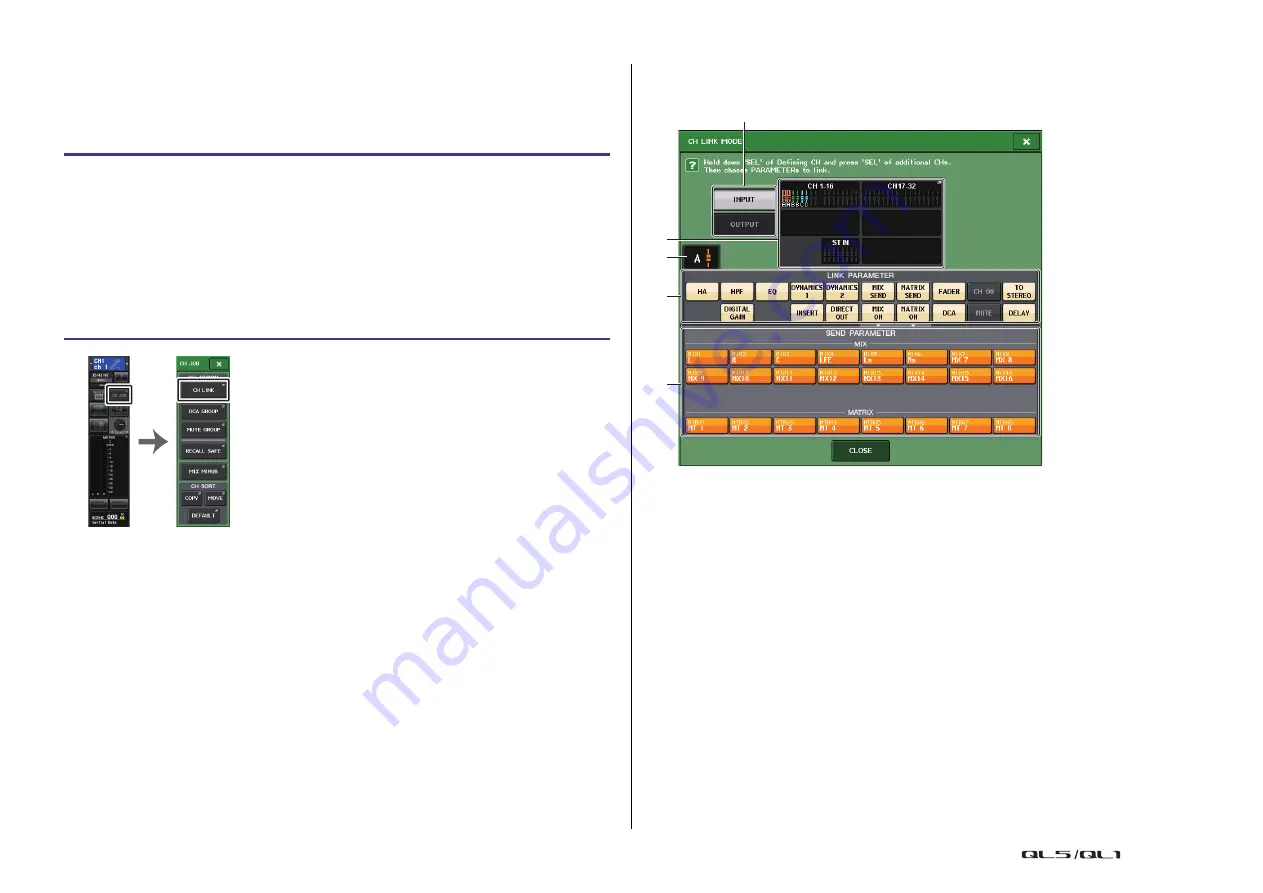
CH LINK MODE window (input channels)
You can view the channels that are linked and specify the parameters that will be linked.
1
Input channel display field
When you create a link group, the corresponding input channels will be highlighted. If
there are two or more link groups, each group is shown in a different color. Press this
field to open the CH LINK SET window. You can also link input channels in this window.
NOTE
• Left and right of the ST IN channel are always linked.
• In the case of the QL1, faders that do not exist on the model will not be shown.
2
Link indicator
If an input channel belonging to a link group is selected, the associated link group is
shown. The LINK PARAMETER field and SEND PARAMETER field show the link settings.
While you hold down the [SEL] key of an input channel that does not belong to any link
group, the link indicator shows the link group that will be created next. The LINK
PARAMETER field and SEND PARAMETER field show the settings of the link group that
had been previously displayed.
STEP
1.
In the Function Access Area, press the CH JOB button.
2.
Press the CH LINK button in the CH JOB menu.
3.
To link channels, hold down the [SEL] key for the link-source input channel and press
the [SEL] key for the link-destination channel.
4.
Use the buttons of the LINK PARAMETER field in the CH LINK MODE window to
select the parameter(s) that will be linked (multiple selections are allowed).
5.
If you turned on the MIX ON, MIX SEND, MATRIX ON, or MATRIX SEND buttons in
step 4, use the buttons of the SEND PARAMETER field to specify the bus(es) for
which you want operations to be linked (multiple selections are allowed).
Function
Access Area
CH JOB
menu
5
2
3
1
4


