Setup
Reference Manual
230
Information messages
The indicators will remain lit /blinking cyclically to report the status.
If the orange [SYNC] indicator is not lit, the unit is operating correctly.
If the green [SYNC] indicator is not lit, the device’s word clock is not defined.
Using GPI (General Purpose Interface)
The rear panel GPI (General Purpose Interface) connector can be used as an input/output
connector. This connector provides five GPI IN ports and five GPI OUT ports. For example
you can use an external switch to control internal parameters of the QL series console or to
switch scenes. Conversely, operations or scene changes performed on the QL series console
can send control signals to an external device.
For details on how to send control signals to an external device when you switch scenes, refer
to “
Outputting a control signal to an external device in tandem with scene recall (GPI OUT)
.
Using GPI IN
You can use the GPI IN ports of the GPI connector to control the parameters of the QL series
console from an external device. For example, you could use an external switch to turn the
QL series console’s Talkback on/off, operate the Tap Tempo function, or switch scenes.
An abnormality has occurred
on the circuit connected to the
SECONDARY connector
during redundant network
operation.
Check the circuit connected to the
SECONDARY connector.
[SYNC] indicators
Meaning
Possible solution
Muted during startup, or in the
process of synchronization.
Please wait until started has
completed or until the unit has
finished synchronization. It may
take up to 45 seconds for
completion.
The device is operating
correctly as a word clock
master.
This indicates that the device is
operating as a word clock master.
The device is operating
correctly as a word clock
slave.
This indicates that the device is
operating as a word clock slave
and synching to the word clock.
Flash x2
Lit or
blinking
Lit
Blinking
Lit
STEP
1.
Connect an external device to the QL series console’s GPI connector.
2.
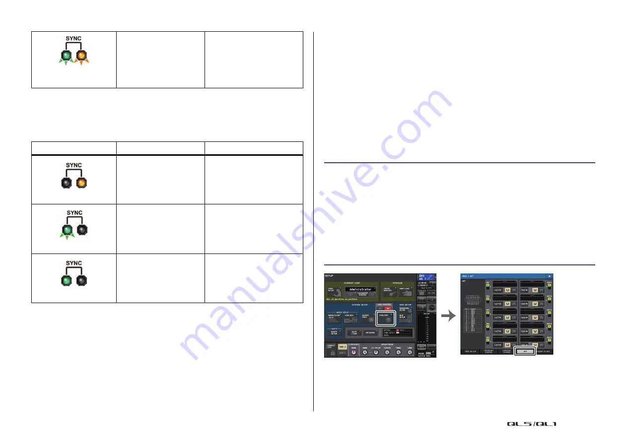
In the Function Access Area, press the SETUP button.
3.
In the SETUP screen, press the MIDI/GPI button.
4.
In the MIDI/GPI screen, press the GPI tab.
5.
Specify the switch attribute and POLARITY MODE for each port as appropriate for
the specifications of the external device you’re using.
6.
To assign the function or parameter that you want to control, press the GPI IN
SETUP button.
7.
In each field of the GPI IN SETUP window, select the desired function and parameter,
then press the OK button.
SETUP screen
MIDI/GPI screen


