Setup
Reference Manual
214
NOTE
• In Surround mode, you cannot use cascade output on MIX buses 1-6. In addition, if you have
selected 5.1 SOLO in CUE mode, you cannot monitor CUE from the cascade slave at the
cascade master.
• If you are making a cascade connection between the QL unit and the PM5D, you can use the QL
unit as the cascade slave by setting the PM5D’s CASCADE IN PORT SELECT to a slot. However,
only the audio signals will be cascaded, and the control signals cannot be linked.
• You can also use an AD/DA card or OMNI OUT jack to make cascade connections with an analog
mixer.
• There is no limit to the number of units that can be cascade-connected, but the signal delay at
the cascade slave will increase in accordance with the number of units from the cascade master.
Operations on a cascade slave QL unit
NOTE
• You cannot assign two or more buses to the same output port. If you select a port to which a
signal route has already been assigned, the previous assignment will be canceled.
• Control signals for the cascade link and MIDI messages cannot share the same port. If you select
a port that is already specified for transmission/reception of MIDI messages, a dialog box will ask
whether it is OK to cancel the existing settings.
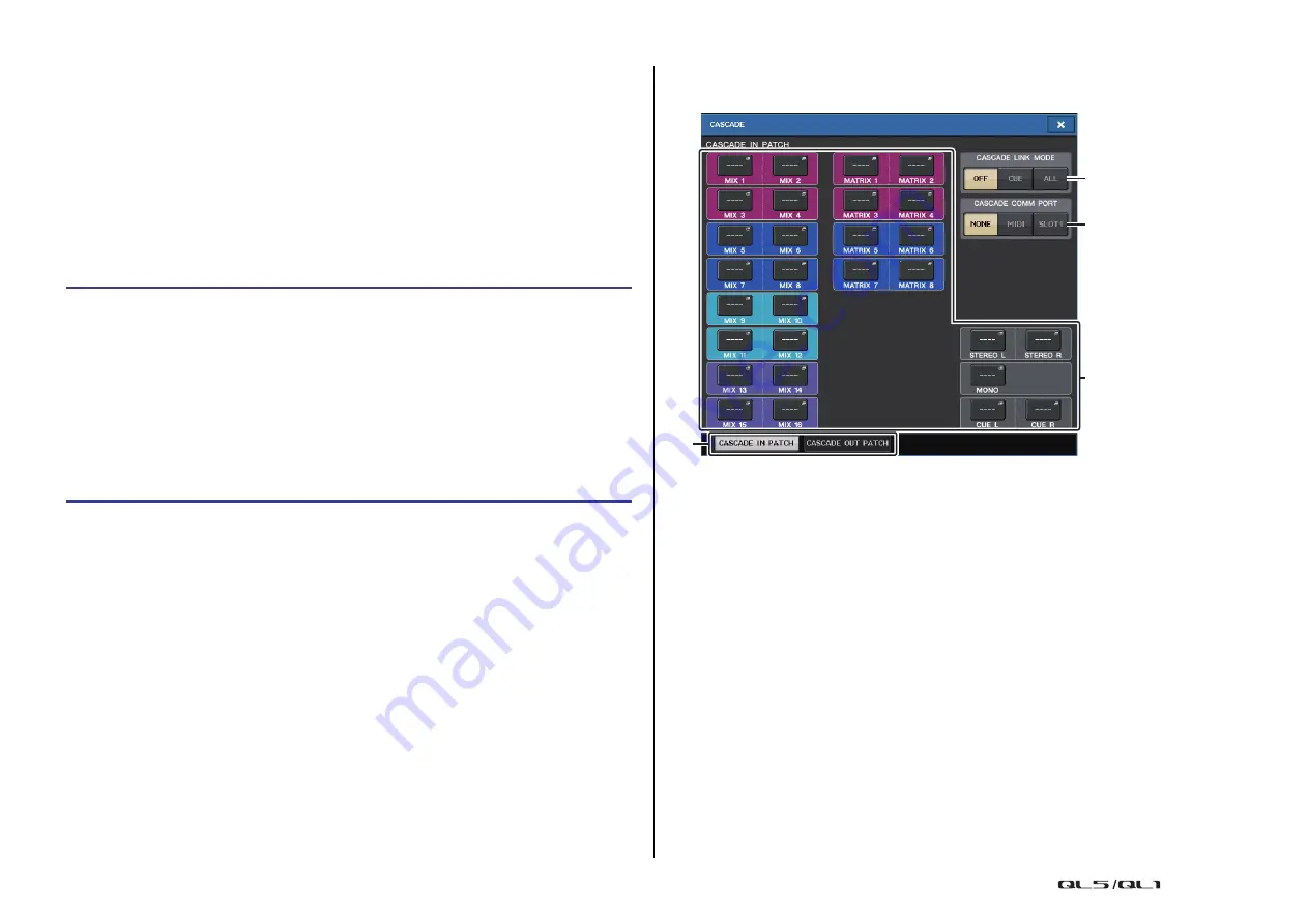
CASCADE window (CASCADE OUT PATCH page)
You can select the slot and output port that will output each bus.
1
Port select popup buttons (CASCADE OUT PATCH section)
Enable you to select the output port for cascade connections for each of MIX 1–16,
MATRIX 1–8, STEREO L/R, MONO, and CUE L/R buses. Press the button to open the
PORT SELECT window, in which you can select a port.
2
CASCADE LINK MODE buttons
Specify whether only cue operations will be linked, or all linkable operations including
scene store/recall operations will also be linked when QL series consoles are cascade-
connected.
• OFF
No link operation
• CUE
The following cue-related parameters and events will be linked.
• Cue enable/disable
• Cue mode (MIX CUE or LAST CUE)
• Cue point settings for input channels and output channels
• ALL
All linkable parameters and events (including cue-related parameters) will be
linked.
• Cue-related parameters and events (see above)
• Scene recall operations
STEP
1.
In the Function Access Area, press the SETUP button.
2.
In the SYSTEM SETUP field of the SETUP screen, press the CASCADE button.
3.
In the CASCADE window, press the CASCADE OUT PATCH tab.
4.
In the CASCADE OUT PATCH page, press the OUT PATCH button for the bus to which
you want to assign the port.
5.
Use the category select list and the port select buttons to select the slot and output
ports that you want to assign, and then press the CLOSE button.
6.
In the CASCADE COMM PORT field, select the port that will transmit and receive
control signals for cascade link.
7.
Use the CASCADE LINK MODE buttons to select the item that you want to link.
3
1
2
4


