


6-24
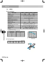
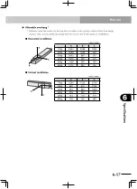
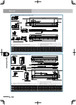
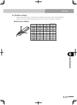
Specifications
6
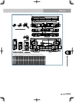
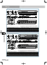
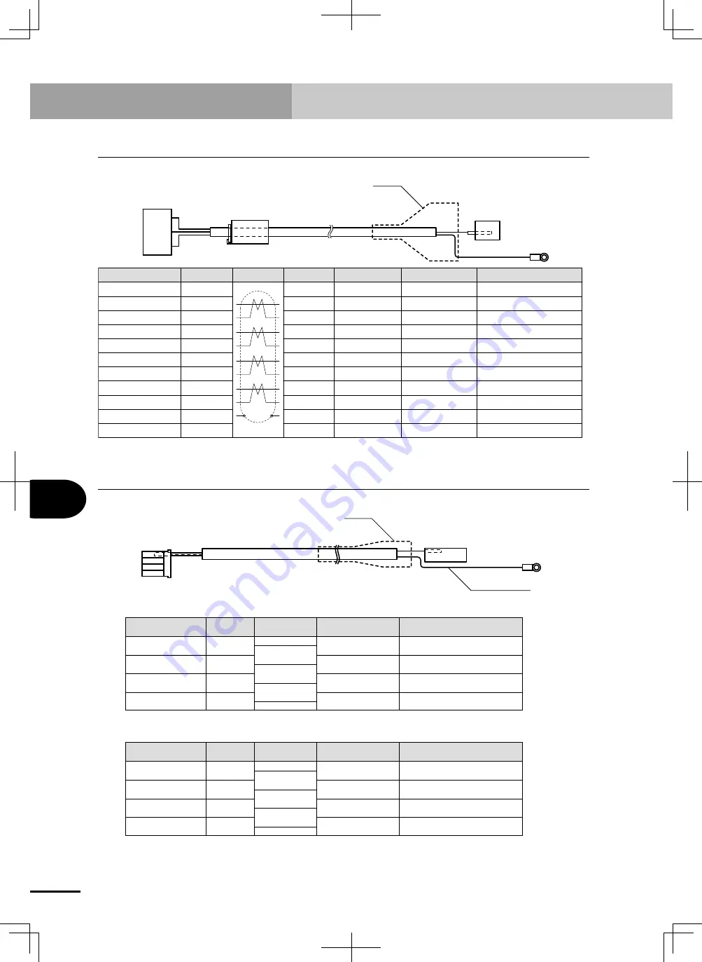
Robot cable (I/O signal wires)
4.
Robot cable (I/O signal wires)
To controller
To robot
Hood
Ground wire
Signal
Robot
Controller CN1
Connect to:
Remarks
Connect to:
Connection Pin No.
Pin No.
1
7
3
6
2
5
4
9
8
0.3 mm
2
Blue
0.3 mm
2
Gray
Orange
Green
Brown
Gray
Red
Black
Yellow
5
1
3
8
2
7
4
20
6
Z+
C+
S-
C-
S+
Z-
FG
+5V
D.G.
Round terminal
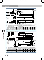
5.
Robot cable (motor wires)
Ground wire
Hood
To controller
To robot
■
SR1/SRCP
Motor wire FG
U
V
W
0.75 mm
2
Yellow/Green
0.75 mm
2
0.75 mm
2
0.75 mm
2
1
2
4
3
Round terminal
1
2
3
Black
White
Red
Signal
Remarks
Connection
Pin No.
Pin No.
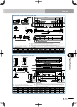
■
RCX
Motor wire FG
U
V
W
0.75 mm
2
Yellow/Green
0.75 mm
2
0.75 mm
2
0.75 mm
2
1
2
3
4
Round terminal
1
2
3
Black
White
Red
Signal
Remarks
Connection
Pin No.
Pin No.
Содержание PHASER MF
Страница 1: ...MF Type EUC021A540 E37 Ver 5 40 User s Manual YAMAHA LINEAR MOTOR ROBOTS PHASER series...
Страница 2: ......
Страница 6: ......
Страница 10: ......
Страница 12: ......
Страница 18: ......
Страница 32: ......
Страница 44: ......
Страница 62: ......
Страница 68: ...5 6 MEMO...
Страница 70: ......
Страница 96: ......