


6-19
6-18
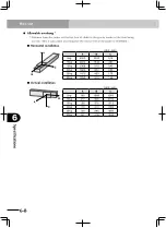
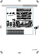
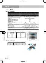
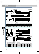
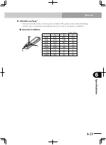
Specifications
6
Main unit
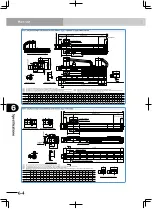
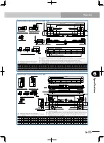
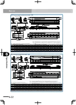
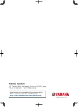
MF30 single carriage horizontal mount model
7
3.7
2.5
4.
5
7.
2
Detail of section G
(100)
(Note 6)
Optional cable carrier S / M type
80:
Top face of slider
64 14
186
(100)
(Note 6)
32.5
150
G
24
15
14
20.5
14
20.5
40
49
29
35
50
66
ф
6.7
ф
7.5
136
Effective stroke
155+/-5 (R side origin position)
(155: When at L side origin)
L
155+/-5 (L side origin position)
(155: When at R side origin)
70
190
54+/-1
(Note 1)
54+/-1
(Note 1)
Grounding terminal (M4)
98
A
B x 200
(A)
200
105
10
0
Cross-section of optional cable carrier
M
S
L
238
Optional cable carrier L type
Note 4
167
(Note 6)
90
4-
ф
6H7
+0.012
0
Depth 10
4-M6 x 1.0 Depth 12
2-
ф
10H7
+0.015
0
Depth 10 (Note 5)
ф
30
Diameter of roller
240.5 (M option)
215.5 (S option)
120 (Between
ф
6H7
+/-0.0
2
)
C-M6 x 1.0 Depth 10
+/-0.02
50
D
+/-0.02
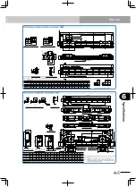
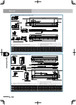
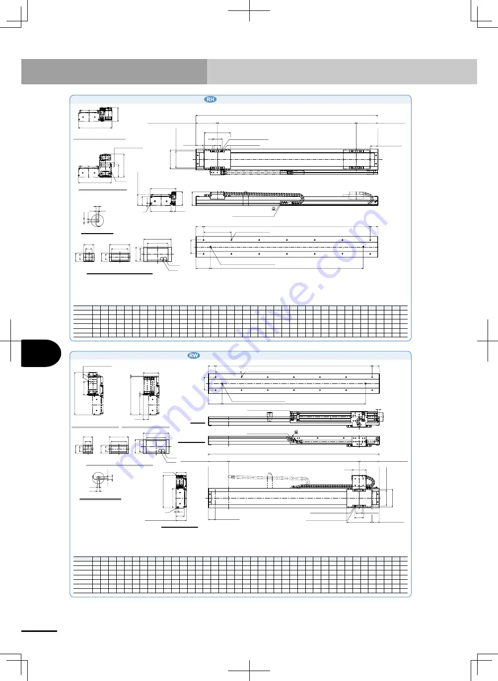
MF30 single carriage wall mount model
24
14
20.
5
15
Cross-section of optional cable carrier
M
S
L
ф
7.5
14
20.
5
40
49
50
66
29
35
ф
6.7
G section detailed chart
4.5
7.2
7
3.
7
2.
5
325
(Note 6)
105
150
9
290
(Note 6)
41.3
(5
)
S type
120.3
G
15
0
25
0
(Note 6)
Optional cable carrier M type
Optional cable carrier L type
14
64
80
Top face of slider
79
(155: When at R side origin)
155+/-5 (R side origin position)
A
B x 200
(A)
200
C-M6 x 1.0 Depth 10
100
105
13
Grounding terminal (M4)
Grounding terminal (M4)
L
Effective stroke
108
190
70
13
6
2-
ф
10H7
+0.015
0
Depth 10 (Note 5)
155+/-5 (L side origin position)
(155: When at L side origin)
54+/-1
(Note 1)
54+/-1
(Note 1)
120 (Between
ф
6H7
+/-0.02
)
4-M6 x 1.0 Depth 12
4-
ф
6H7
+0.012
0
Depth 10
ф
30
Diameter of roller
+/-0.02
50
D
+/-0.02
Standard, Stype
Standard and S types
M, Ltype
Note. Stop positions are determined by the mechanical stoppers at both ends.
Note. The origin is set on the R side at the time of shipment. It can be changed to the L side by parameter
setting.
Note. For models with a 2,100mm or longer stroke, optional L type cable carriers can only be used.
Note. For models with a 3,000mm or longer stroke and an optional L type cable carrier, a roller is
installed to prevent the cable carrier from sagging.
Note. When using
ф
10 H7 hole, do not insert the pin more than the depth stated in the drawing.
Otherwise, the motor may break.
Note. Depending on the stroke and the operating conditions, the cable carrier bending radius might
be larger, making it higher than the dimensions shown in the diagram.
Effective stroke 100 200 300 400 500 600 700 800 9001000110012001300140015001600170018001900200021002200230024002500260027002800290030003100320033003400350036003700380039004000
L
410 510 610 710 810 910 10101110 12101310141015101610171018101910201021102210231024102510261027102810291030103110321033103410351036103710381039104010411042104310
A
105 55 105 55 105 55 105 55 105 55 105 55 105 55 105 55 105 55 105 55 105 55 105 55 105 55 105 55 105 55 105 55 105 55 105 55 105 55 105 55
B
1
2
2
3
3
4
4
5
5
6
6
7
7
8
8
9
9 10 10 11 11 12 12 13 13 14 14 15 15 16 16 17 17 18 18 19 19 20 20 21
C
4
6
6
8
8 10 10 12 12 14 14 16 16 18 18 20 20 22 22 24 24 26 26 28 28 30 30 32 32 34 34 36 36 38 38 40 40 42 42 44
D
200 300 400 500 600 700 800 90010001100 120013001400150016001700180019002000210022002300240025002600270028002900300031003200330034003500360037003800390040004100
E
220 270 320 370 420 470 520 570 620 670 720 770 820 870 920 970 10201070 1120 11701220127013201370142014701520157016201670172017701820187019201970202020702120 2170
Weight (kg)
9.0 10.712.313.915.6 17.2 18.820.422.123.725.327.028.630.231.933.535.136.738.440.041.643.344.946.548.249.851.453.054.756.357.959.661.262.864.566.1 67.7 69.371.0 72.6
Note. Stop positions are determined by the mechanical stoppers at both ends.
Note. The origin is set on the L side at the time of shipment. It can be changed to the R side by parameter
setting.
Note. For models with a 2,100mm or longer stroke, optional L type cable carriers can only be used.
Note. For models with a 3,000mm or longer stroke and an optional L type cable carrier, a roller is
installed to prevent the cable carrier from sagging.
Note. When using
ф
10 H7 hole, do not insert the pin more than the depth stated in the drawing.
Otherwise, the motor may break.
Note. Depending on the stroke and the operating conditions, the cable carrier bending radius might
be larger, making it higher than the dimensions shown in the diagram.
Effective stroke 100 200 300 400 500 600 700 800 9001000110012001300140015001600170018001900200021002200230024002500260027002800290030003100320033003400350036003700380039004000
L
410 510 610 710 810 910 10101110 12101310141015101610171018101910201021102210231024102510261027102810291030103110321033103410351036103710381039104010411042104310
A
105 55 105 55 105 55 105 55 105 55 105 55 105 55 105 55 105 55 105 55 105 55 105 55 105 55 105 55 105 55 105 55 105 55 105 55 105 55 105 55
B
1
2
2
3
3
4
4
5
5
6
6
7
7
8
8
9
9 10 10 11 11 12 12 13 13 14 14 15 15 16 16 17 17 18 18 19 19 20 20 21
C
4
6
6
8
8 10 10 12 12 14 14 16 16 18 18 20 20 22 22 24 24 26 26 28 28 30 30 32 32 34 34 36 36 38 38 40 40 42 42 44
D
200 300 400 500 600 700 800 90010001100 120013001400150016001700180019002000210022002300240025002600270028002900300031003200330034003500360037003800390040004100
Weight (kg)
9.0 10.712.313.915.6 17.2 18.820.422.123.725.327.028.630.231.933.535.136.738.440.041.643.344.946.548.249.851.453.054.756.357.959.661.262.864.566.1 67.7 69.371.0 72.6
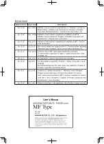
Содержание PHASER MF
Страница 1: ...MF Type EUC021A540 E37 Ver 5 40 User s Manual YAMAHA LINEAR MOTOR ROBOTS PHASER series...
Страница 2: ......
Страница 6: ......
Страница 10: ......
Страница 12: ......
Страница 18: ......
Страница 32: ......
Страница 44: ......
Страница 62: ......
Страница 68: ...5 6 MEMO...
Страница 70: ......
Страница 96: ......