6-9
6-8
6
Specifications
Main unit
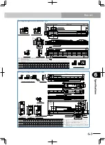
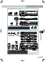
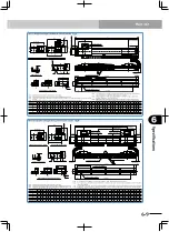
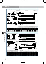
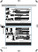
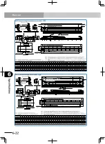
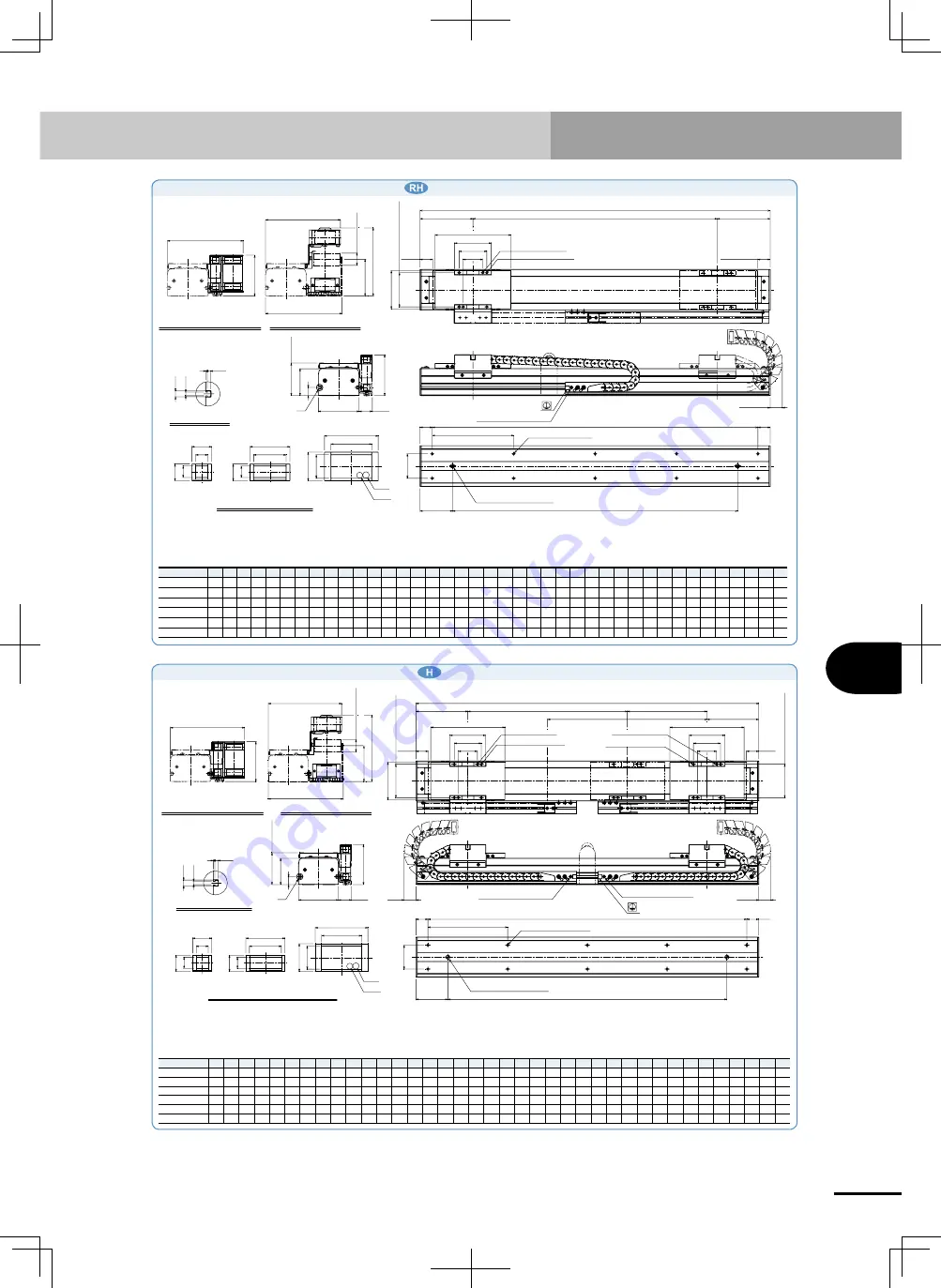
MF15 single carriage horizontal mount model
6W\SH
1RWH
2SWLRQDOFDEOHFDUULHU60W\SH
1RWH
2SWLRQDOFDEOHFDUULHU/W\SH
7RSIDFHRIVOLGHU
%
HWZHHQ
ǐ
+
1RWH
1RWH
/VLGHRULJLQSRVLWLRQ
:KHQDW5VLGHRULJLQ
(IIHFWLYHVWURNH
5VLGHRULJLQSRVLWLRQ
:KHQDW/VLGHRULJLQ
ǐ
+'HSWK
1RWH
/
*URXQGLQJWHUPLQDO0
1RWH
*
1RWH
'HWDLORIVHFWLRQ*
/
6
&URVVVHFWLRQRIFDEOHFDUULHU
ǐ
ǐ
0
$
%[
$
&0['HSWK
ǐ
+'HSWK
'
0['HSWK
ǐ
'LDPHWHURIUROOHU
0W\SH
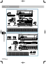
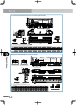
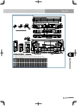
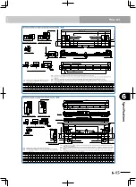
MF15D double carriage horizontal mount model
6HFWLRQGUDZLQJRIRSWLRQDOFDEOHFDUULHU
1RWH
1RWH
1RWH
1RWH
/
(IIHFWLYHVWURNH
(IIHFWLYHVWURNH
0LQLPXPGLVWDQFHEHWZHHQFDUULDJHV
0['HSWK
0['HSWK
*URXQGLQJWHUPLQDO0
*URXQGLQJWHUPLQDO0
1RWH
1RWH
7RSIDFHRIVOLGHU
1RWH
*
ǐ
ǐ
$
%[
$
&0['HSWK
/
6
0
1RWH
1RWH
ǐ
+'HSWK
ǐ
+'HSWK
ǐ
+'HSWK
1RWH
0W\SH
6W\SH
2SWLRQDOFDEOHFDUULHU60W\SH
ǐ
'LDPHWHURIUROOHU
2SWLRQDOFDEOHFDUULHU/W\SH
*VHFWLRQGHWDLOHGFKDUW
'
%HWZHHQ
ǐ
+
%HWZHHQ
ǐ
+
Note. Position of the table slider when returned to the origin.
Note. Stop positions are determined by the mechanical stoppers at both ends.
Note. Protrusion is the distance the cable carrier extends from the edge of unit
when an optional L type cable carrier is used.
Note. For models with a 2,100mm or longer stroke, optional L type cable carriers can only be used.
Note. For models with a 3,000mm or longer stroke and an optional L type cable carrier, a roller is installed to prevent the cable
carrier from sagging.
Note. When using
ф
10 H7 hole, do not insert the pin more than the depth stated in the drawing. Otherwise, the motor may break.
Note. Depending on the stroke and the operating conditions, the cable carrier bending radius might be larger, making it higher
than the dimensions shown in the diagram.
Effective stroke 100 200 300 400 500 600 700 800 900 10001100120013001400150016001700180019002000210022002300240025002600270028002900300031003200330034003500360037003800
L
560 660 760 860 960 10601160 1260136014601560166017601860196020602160226023602460256026602760286029603060316032603360346035603660376038603960406041604260
A
80 30 80 30 80 30 80 30 80 30 80 30 80 30 80 30 80 30 80 30 80 30 80 30 80 30 80 30 80 30 80 30 80 30 80 30 80 30
B
2
3
3
4
4
5
5
6
6
7
7
8
8
9
9 10 10 11 11 12 12 13 13 14 14 15 15 16 16 17 17 18 18 19 19 20 20 21
C
6
8
8 10 10 12 12 14 14 16 16 18 18 20 20 22 22 24 24 26 26 28 28 30 30 32 32 34 34 36 36 38 38 40 40 42 42 44
D
400 500 600 700 800 900 10001100 120013001400150016001700180019002000210022002300240025002600270028002900300031003200330034003500360037003800390040004100
Weight (kg)
10.3 11.5 12.613.714.816.0 17.1 18.219.320.521.622.723.825.026.1 27.228.329.530.631.732.834.035.136.237.438.539.641.042.243.344.445.546.7 47.848.950.051.252.3
Note. Position of the table slider when returned to the origin.
Note. Stop positions are determined by the mechanical stoppers at both ends.
Note. Protrusion is the distance the cable carrier extends from the edge of unit when an optional L type cable carrier
is used.
Note. For models with a 2,100mm or longer stroke, optional L type cable carriers can only be used.
Note. For models with a 3,000mm or longer stroke and an optional L type cable carrier, a
roller is installed to prevent the cable carrier from sagging.
Note. When using
ф
10 H7 hole, do not insert the pin more than the depth stated in the
drawing. Otherwise, the motor may break.
Note. Depending on the stroke and the operating conditions, the cable carrier bending
radius might be larger, making it higher than the dimensions shown in the diagram.
Effective stroke 100 200 300400500600 700 8009001000110012001300140015001600170018001900200021002200230024002500260027002800290030003100320033003400350036003700380039004000
L
360 460 560660 760 86096010601160126013601460156016601760186019602060216022602360246025602660276028602960306031603260336034603560366037603860396040604160 4260
A
80 30 80 30 80 30 80 30 80 30 80 30 80 30 80 30 80 30 80 30 80 30 80 30 80 30 80 30 80 30 80 30 80 30 80 30 80 30 80 30
B
1 2 2 3 3 4 4 5 5 6 6 7 7 8 8 9 9 10 10 11 11 12 12 13 13 14 14 15 15 16 16 17 17 18 18 19 19 20 20 21
C
4 6 6 8 8 10 10 12 12 14 14 16 16 18 18 20 20 22 22 24 24 26 26 28 28 30 30 32 32 34 34 36 36 38 38 40 40 42 42 44
D
200 300 400500600700 80090010001100 120013001400150016001700180019002000210022002300240025002600270028002900300031003200330034003500360037003800390040004100
Weight (kg)
6.3 7.3 8.3 9.3 10.3 11.3 12.3 13.3 14.3 15.4 16.4 17.4 18.4 19.4 20.4 21.4 22.423.424.4 25.426.4 27.4 28.429.430.4 31.4 32.433.434.435.836.8 37.8 38.839.840.8 41.8 42.843.844.845.8
Содержание PHASER MF
Страница 1: ...MF Type EUC021A540 E37 Ver 5 40 User s Manual YAMAHA LINEAR MOTOR ROBOTS PHASER series...
Страница 2: ......
Страница 6: ......
Страница 10: ......
Страница 12: ......
Страница 18: ......
Страница 32: ......
Страница 44: ......
Страница 62: ......
Страница 68: ...5 6 MEMO...
Страница 70: ......
Страница 96: ......


