


2-5
2-4
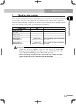
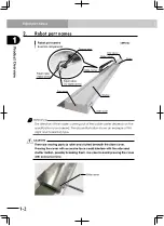
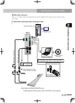
Robot installation conditions
Installation and connections
2
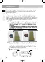
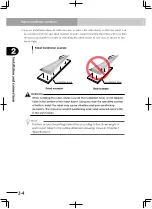
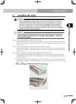
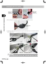
3) Use an installation base of sufficient size to match the robot body so that the robot can
be installed with the specified number of bolts. Avoid installing the robot with less than
the specified number of bolts or installing the robot closer to one end as shown at the
lower right.
Good example
Installation base
Bad example
Installation base
Robot installation example
w
WARNING
When installing the robot, always use all the installation holes or m8 tapped
holes in the bottom of the robot frame. Using less than the specified number
of bolts to install the robot may cause vibration and poor positioning
accuracy. This may also result in positioning errors and reduced service life
in the worst cases.
n
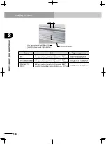
NOTE
Positions of robot mounting holes differ according to the stroke length of
each robot. Refer to the outline dimension drawings shown in Chapter 7,
"Specifications".
Содержание PHASER MF
Страница 1: ...MF Type EUC021A540 E37 Ver 5 40 User s Manual YAMAHA LINEAR MOTOR ROBOTS PHASER series...
Страница 2: ......
Страница 6: ......
Страница 10: ......
Страница 12: ......
Страница 18: ......
Страница 32: ......
Страница 44: ......
Страница 62: ......
Страница 68: ...5 6 MEMO...
Страница 70: ......
Страница 96: ......