


10
MODX6/MODX7
■
DISASSEMBLY PROCEDURE
(分解手順)
Precaution
(注意事項)
* Attach the filament tapes in the same way as they
were before removal.
※ フィラメントテープは、取り外す前と同じように取り
付けてください。
* Notes on Flat Cable
Contacts are visible through the back side. When
connecting to the connector, pay attention not to
insert the cable inversely. (Photo 1)
※ フラットケーブル注意
接点が裏面から透けて見えます。コネクタにケーブル
の表・裏を逆に差し込まないように注意して取り付け
てください。(写真 1)
* During assembly, pay attention that connectors,
cables or the like are not pinched by circuit boards,
frames, etc.
※ 組み立てるときは、基板やフレームなどでコード類を
はさまないように注意してください。
Photo 1 (写真 1)
CONTENTS
1.
Upper Case Assembly, Lower Case Assembly. . . . . . 10
2.
Circuit Boards and Assemblies (Lower Case Section). . 12
3.
Circuit Boards and Assemblies (Upper Case Section). . 13
4.
PNR Circuit Board . . . . . . . . . . . . . . . . . . . . . . . . . . . . 14
5.
PNC Circuit Board . . . . . . . . . . . . . . . . . . . . . . . . . . . . 14
6.
LCD Display . . . . . . . . . . . . . . . . . . . . . . . . . . . . . . . . . 15
7.
MODX6 Disassembling the Keyboard Assembly . . . . 16
8.
MODX7 Disassembling the Keyboard Assembly . . . . 18
目次
1.
上ケース Ass’y、下ケース Ass’y . . . . . . . . . . . . . . . . . 10
2.
基板とアッセンブリ(下ケース部). . . . . . . . . . . . . . . . 12
3.
基板とアッセンブリ(上ケース部). . . . . . . . . . . . . . . . 13
4.
PNR シート . . . . . . . . . . . . . . . . . . . . . . . . . . . . . . . . . . 14
5.
PNC シート . . . . . . . . . . . . . . . . . . . . . . . . . . . . . . . . . . 14
6.
液晶ディスプレイ . . . . . . . . . . . . . . . . . . . . . . . . . . . . . 15
7.
MODX6 鍵盤 Ass’y の分解 . . . . . . . . . . . . . . . . . . . . . . 16
8.
MODX7 鍵盤 Ass’y の分解 . . . . . . . . . . . . . . . . . . . . . . 18
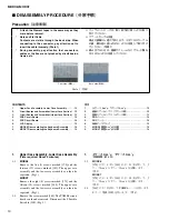
Front side (
表面
)
Back side (
裏面
)
1.
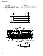
Upper Case Assembly, Lower Case Assembly
(Time required: About 4 minutes)
1-1.
MODX6
Remove the five (5) screws marked [170] and the
thirteen (13) screws marked [180]. The upper case
assembly and the lower case assembly can then be
separated. (Fig.1)
MODX7
Remove the eight (8) screws marked [170] and the
fifteen (15) screws marked [180]. The upper case
assembly and the lower case assembly can then be
separated. (Fig.1)
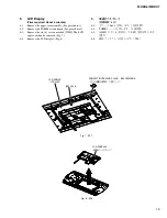
1-2.
Remove the screw marked [160]. The TOME4 circuit
board can then be removed. Disconnect the S flexible
flat cable (50P). (Fig. 2)
1.
上ケース Ass’y、下ケース Ass’y
(所要時間:約 4 分)
1-1.
MODX6
[170] のネジ 5 本と [180] のネジ 13 本を外して、上
ケース Ass’y と下ケース Ass’y を分離します 。
(図 1)
MODX7
[170] のネジ 8 本と [180] のネジ 15 本を外して、上
ケース Ass’y と下ケース Ass’y を分離します 。
(図 1)
1-2.
[160] のネジ 1 を外して、TOME4 シートを外します。
S カード電線 (50P) を外します 。(図 2)
Содержание MODX6
Страница 23: ...23 MODX6 MODX7 C C Pattern side DM Circuit Board C C 2NA ZW84620 1...
Страница 24: ...MODX6 MODX7 24 PNC Circuit Board Component side 2NA ZX42110...
Страница 28: ...MODX6 MODX7 28 PNR Circuit Board Component side 2NA ZX42110...
Страница 29: ...29 MODX6 MODX7 to PNC CB107 Pattern side PNR Circuit Board 2NA ZX42110...
Страница 31: ...31 MODX6 MODX7 TOME4 Circuit Board Component side Pattern side 2NA ZX42110...
Страница 32: ...MODX6 MODX7 32 2NAK8 V869520 1 61L Circuit Board Component side D D D D to 61H CN3 to KEY IF CB504...
Страница 35: ...35 MODX6 MODX7 76H Circuit Board 2NAK8 ZW58960 Component side to KEY IF CB508 to 76L CN3 G G G G H H H H...
Страница 73: ...73 MODX6 MODX7 3 Searching for the updater 4 Searching for the updater OK 5 Finish Please turn off 6 USB 7 8 22...
Страница 74: ...MODX6 MODX7 74 SYSTEM BOOTING FLOWCHART...
Страница 99: ...14 MODX6 MODX7 MODX6 KEYBOARD ASSEMBLY Ass y 120 120 220 100 151 152 100 10 10 30 50 50 60 85 90 80 20 40 40 20...