MIDI Data Table
70
Data List
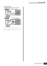
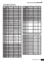
TOTAL SIZE = 34
22 (HEX)
TOTAL SIZE = 30
1E (HEX)
TOTAL SIZE = 38
26 (HEX)
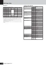
Address
Size
Data
Range
(HEX)
Parameter Name
Description
Notes
40
04
00
2
00 – 7F
00 – 7F
Insertion-B Type MSB
Insertion-B Type LSB
Refer to “Effect
Parameter List.”
02
2
00 – 7F
00 – 7F
Insertion-B Parameter 1 MSB
Insertion-B Parameter 1 LSB
:
04
2
00 – 7F
00 – 7F
Insertion-B Parameter 2 MSB
Insertion-B Parameter 2 LSB
:
06
2
00 – 7F
00 – 7F
Insertion-B Parameter 3 MSB
Insertion-B Parameter 3 LSB
:
08
2
00 – 7F
00 – 7F
Insertion-B Parameter 4 MSB
Insertion-B Parameter 4 LSB
:
0A
2
00 – 7F
00 – 7F
Insertion-B Parameter 5 MSB
Insertion-B Parameter 5 LSB
:
0C
2
00 – 7F
00 – 7F
Insertion-B Parameter 6 MSB
Insertion-B Parameter 6 LSB
:
0E
2
00 – 7F
00 – 7F
Insertion-B Parameter 7 MSB
Insertion-B Parameter 7 LSB
:
10
2
00 – 7F
00 – 7F
Insertion-B Parameter 8 MSB
Insertion-B Parameter 8 LSB
:
12
2
00 – 7F
00 – 7F
Insertion-B Parameter 9 MSB
Insertion-B Parameter 9 LSB
:
14
2
00 – 7F
00 – 7F
Insertion-B Parameter 10 MSB
Insertion-B Parameter 10 LSB
:
16
2
00 – 7F
00 – 7F
Insertion-B Parameter 11 MSB
Insertion-B Parameter 11 LSB
:
18
2
00 – 7F
00 – 7F
Insertion-B Parameter 12 MSB
Insertion-B Parameter 12 LSB
:
1A
2
00 – 7F
00 – 7F
Insertion-B Parameter 13 MSB
Insertion-B Parameter 13 LSB
:
1C
2
00 – 7F
00 – 7F
Insertion-B Parameter 14 MSB
Insertion-B Parameter 14 LSB
:
1E
2
00 – 7F
00 – 7F
Insertion-B Parameter 15 MSB
Insertion-B Parameter 15 LSB
:
20
2
00 – 7F
00 – 7F
Insertion-B Parameter 16 MSB
Insertion-B Parameter 16 LSB
:
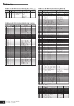
Address
Size
Data
Range
(HEX)
Parameter Name
Description
Notes
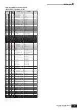
40
05
00
1
00 – 0C
Controller Set 1 Source
0: PB, 1: MW, 3: AT,
4: FC, 5: FS, 6: RB,
7: BC, 8: AS1, 9: AS2,
12: FC2
01
2
00
00 – 44
Controller Set 1 Destination MSB
Controller Set 1 Destination LSB
0 – 68
03
1
00 – 7F
Controller Set 1 Depth
-64 – +63
04
1
reserved
05
1
00 – 0C
Controller Set 2 Source
0: PB, 1: MW, 3: AT,
4: FC, 5: FS, 6: RB,
7: BC, 8: AS1, 9: AS2,
12: FC2
06
2
00
00 – 44
Controller Set 2 Destination MSB
Controller Set 2 Destination LSB
0 – 68
08
1
00 – 7F
Controller Set 2 Depth
-64 – +63
09
1
reserved
0A
1
00 – 0C
Controller Set 3 Source
0: PB, 1: MW, 3: AT,
4: FC, 5: FS, 6: RB,
7: BC, 8: AS1, 9: AS2,
12: FC2
0B
2
00
00 – 44
Controller Set 3 Destination MSB
Controller Set 3 Destination LSB
0 – 68
0D
1
00 – 7F
Controller Set 3 Depth
-64 – +63
0E
1
reserved
0F
1
00 – 0C
Controller Set4 Source
0: PB, 1: MW, 3: AT,
4: FC, 5: FS, 6: RB,
7: BC, 8: AS1, 9: AS2,
12: FC2
10
2
00
00 – 44
Controller Set 4 Destination MSB
Controller Set 4 Destination LSB
0 – 68
12
1
00 – 7F
Controller Set 4 Depth
-64 – +63
13
1
reserved
14
1
00 – 0C
Controller Set 5 Source
0: PB, 1: MW, 3: AT,
4: FC, 5: FS, 6: RB,
7: BC, 8: AS1, 9: AS2,
12: FC2
15
2
00
00 – 44
Controller Set 5 Destination MSB
Controller Set 5 Destination LSB
0 – 68
17
1
00 – 7F
Controller Set 5 Depth
-64 – +63
18
1
reserved
19
1
00 – 0C
Controller Set 6 Source
0: PB, 1: MW, 3: AT,
4: FC, 5: FS, 6: RB,
7: BC, 8: AS1, 9: AS2,
12: FC2
1A
2
00
00 – 44
Controller Set 6 Destination MSB
Controller Set 6 Destination LSB
0 – 68
1C
1
00 – 7F
Controller Set 6 Depth
-64 – +63
1D
1
reserved
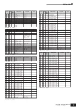
Address
Size
Data
Range
(HEX)
Parameter Name
Description
Notes
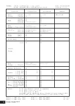
40
06
00
1
00 – 05
LFO Phase
0, 90, 120, 180, 240, 270
01
1
00 – 0C
LFO Wave
tri, tri+, sawup, sawdwn,
squ1/4, squ1/3, squ, squ2/3,
squ3/4, trpzd, S/H1, S/H2,
user
02
1
00 – 3F
LFO Speed
0 – 63
(available only when the
Tempo Sync is set to off)
03
1
05 – 15
LFO Tempo Speed
5 – 21
(available only when the
Tempo Sync is set to on)
16th, 8th/3,
16th., 8th,
4th/3, 8th.,
4th, 2th/3,
4th., 2nd,
Whole/3, 2nd.,
4thX4, 4thX5,
4thX6, 4thX7,
4thX8
04
1
00 – 01
LFO Tempo Sync
OFF, ON
05
1
00 – 7F
LFO Delay Time
0 – 127
06
1
00 – 7F
LFO Fade In Time
0 – 127
07
1
00 – 7F
LFO Hold Time
0 – 127
08
1
00 – 7F
LFO Fade Out Time
0 – 127
09
1
00 – 02
LFO Key On Reset
off, each-on, 1st-on
0A
1
00 – 05
LFO Box 1 Destination
AMD, PMD, FMD, RESO,
PAN, ELEMENT LFO SPEED
0B
1
00 – 7F
LFO Box 1 Depth
0 – 127
0C
1
reserved
0D
1
00 – 05
LFO Box 2 Destination
AMD, PMD, FMD, RESO,
PAN, ELEMENT LFO SPEED
0E
1
00 – 7F
LFO Box 2 Depth
0 – 127
0F
1
reserved
10
1
00 – 05
LFO Box 3 Destination
AMD, PMD, FMD, RESO,
PAN, ELEMENT LFO SPEED
11
1
00 – 7F
LFO Box 3 Depth
0 – 127
12
1
reserved
13
1
00 – 06
User Wave Total Step
2, 3, 4, 6, 8, 12, 16
14
1
00 – 03
User Wave Slope
OFF, UP, DOWN, UP&DOWN
15
1
00 – 7F
User Wave Step Value 1
0 – 127
16
1
00 – 7F
User Wave Step Value 2
0 – 127
17
1
00 – 7F
User Wave Step Value 3
0 – 127
18
1
00 – 7F
User Wave Step Value 4
0 – 127
19
1
00 – 7F
User Wave Step Value 5
0 – 127
1A
1
00 – 7F
User Wave Step Value 6
0 – 127
1B
1
00 – 7F
User Wave Step Value 7
0 – 127
1C
1
00 – 7F
User Wave Step Value 8
0 – 127
1D
1
00 – 7F
User Wave Step Value 9
0 – 127
1E
1
00 – 7F
User Wave Step Value 10
0 – 127
1F
1
00 – 7F
User Wave Step Value 11
0 – 127
20
1
00 – 7F
User Wave Step Value 12
0 – 127
21
1
00 – 7F
User Wave Step Value 13
0 – 127
22
1
00 – 7F
User Wave Step Value 14
0 – 127
23
1
00 – 7F
User Wave Step Value 15
0 – 127
24
1
00 – 7F
User Wave Step Value 16
0 – 127
25
1
00 – 7F
LFO Random Speed Depth
0 – 127


