


FUEL TANK
7-2
EAS26630
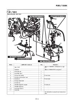
REMOVING THE FUEL TANK
1. Extract the fuel in the fuel tank through the
fuel tank filler hole with a pump.
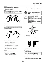
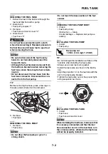
2. Disconnect:
• Fuel pump coupler “1”
3. Remove:
• Fuel hose connector cover “2”
4. Disconnect:
• Fuel hose “3”
WARNING
EWA1SD1017
Cover fuel hose connection with a cloth
when disconnecting it. Residual pressure in
the fuel lines could cause fuel to spurt out
when removing the hose.
NOTICE
ECA37P1023
• Be sure to disconnect the fuel hose by
hand. Do not forcefully disconnect the
hose with tools.
• Although the fuel has been removed from
the fuel tank, be careful when removing the
fuel hose, since there may be fuel remain-
ing in it.
• Do not disconnect the fuel hose from the
fuel hose connector. Disconnect the con-
nector from the fuel pump.
TIP
Before removing the hose, place a few rags in
the area under where it will be removed.
5. Remove:
• Fuel tank
EAS26640
REMOVING THE FUEL PUMP
1. Remove:
• Fuel pump
NOTICE
ECA14720
• Do not drop the fuel pump or give it a
strong shock.
• Do not touch the base section of the fuel
sender.
EAS26670
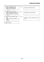
CHECKING THE FUEL PUMP BODY
1. Check:
• Fuel pump body
Obstruction
→
Clean.
Cracks/damage
→
Replace fuel pump as-
sembly.
EAS26700
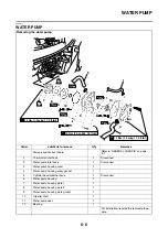
INSTALLING THE FUEL PUMP
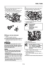
1. Install:
• Fuel pump
TIP
• Do not damage the installation surfaces of the
fuel tank when installing the fuel pump.
• Always use a new fuel pump gasket.
• Install the fuel pump as shown in the illustra-
tion.
• Align the projection “a” on the fuel tank with the
slot in the fuel pump bracket.
• Tighten the fuel pump nuts in the proper tight-
ening sequence as shown.
EAS37P1072
INSTALLING THE FUEL TANK
1. Install:
• Fuel hose
• Fuel hose connector cover
NOTICE
ECA1SD1015
When installing the fuel hose, make sure that
it is securely connected, and that the fuel
hose connector cover on the fuel hose is in
the correct position, otherwise the fuel hose
will not be properly installed.
2
1
3
T
R
.
.
Fuel pump nut
10 Nm (1.0 m·kgf, 7.2 ft·lbf)
1
2
3
4
a
5
6
FWD
Содержание MBK XMAX 2014
Страница 1: ...2014 SERVICE MANUAL YP125R YP125RA 2DM F8197 E0 ...
Страница 6: ......
Страница 8: ......
Страница 64: ...TIGHTENING TORQUES 2 17 Muffler tightening sequence 1 2 3 ...
Страница 72: ...LUBRICATION SYSTEM DIAGRAMS 2 25 EAS2DM1116 LUBRICATION SYSTEM DIAGRAMS 1 2 3 4 5 3 ...
Страница 73: ...LUBRICATION SYSTEM DIAGRAMS 2 26 1 Camshaft 2 Crankshaft 3 Oil pump 4 Oil filter 5 Oil strainer ...
Страница 78: ...CABLE ROUTING 2 31 Steering head front view 1 2 3 4 5 6 8 8 A 7 7 ...
Страница 80: ...CABLE ROUTING 2 33 Front brake left side view for YP125R 1 2 2 1 1 2 2 D E A B C ...
Страница 82: ...CABLE ROUTING 2 35 Front brake left side view for YP125RA 2 1 1 2 1 2 2 A B D E C ...
Страница 84: ...CABLE ROUTING 2 37 Engine and rear brake left side and right side view for YP125R B 2 1 2 1 2 A A 3 3 C ...
Страница 86: ...CABLE ROUTING 2 39 Engine and rear brake left side and right side view for YP125RA 1 2 1 2 2 A A B 3 4 3 4 4 ...
Страница 92: ...CABLE ROUTING 2 45 Frame right side view 3 2 4 1 2 3 A B 6 5 3 A B 3 3 2 3 3 A A B A B B 3 ...
Страница 94: ...CABLE ROUTING 2 47 Engine right side view 6 6 6 6 C D C D D C 10 B 9 5 6 1 2 8 3 4 5 6 7 A ...
Страница 98: ...CABLE ROUTING 2 51 Frame left side view C D C D 2 1 E 1 2 D C 6 1 4 5 3 2 1 7 3 2 1 A B ...
Страница 100: ...CABLE ROUTING 2 53 Engine left side view 1 1 1 1 1 2 3 4 5 6 7 8 9 7 7 A B A B A B 1 ...
Страница 102: ...CABLE ROUTING 2 55 Frame top view 7 8 9 10 11 12 13 13 17 19 19 A D B C 14 C B 1 2 3 4 5 6 14 15 16 18 19 ...
Страница 104: ...CABLE ROUTING 2 57 Engine and frame top view 1 2 4 5 6 7 8 9 10 11 12 13 1 4 5 6 7 8 1 3 10 11 6 8 C 3 11 B A B A 3 ...
Страница 106: ...CABLE ROUTING 2 59 Rear brake right side view 2 2 2 2 2 2 1 1 2 3 A B C 3 ...
Страница 108: ...CABLE ROUTING 2 61 Hydraulic unit for YP125RA 3 2 1 2 3 3 2 2 3 2 2 2 3 3 3 4 4 1 1 4 2 6 B A A 5 1 5 1 5 ...
Страница 110: ...CABLE ROUTING 2 63 ...
Страница 228: ...REAR SHOCK ABSORBER ASSEMBLIES AND SWINGARM 4 89 ...
Страница 231: ......
Страница 291: ...CRANKSHAFT 5 60 a 1 ...
Страница 292: ...CRANKSHAFT 5 61 ...
Страница 302: ...WATER PUMP 6 9 ...
Страница 313: ......
Страница 329: ...CHARGING SYSTEM 8 16 2 AC magneto 3 Rectifier regulator 12 Battery 13 Main fuse 17 Frame ground ...
Страница 331: ...CHARGING SYSTEM 8 18 ...
Страница 349: ...COOLING SYSTEM 8 36 ...
Страница 391: ...FUEL PUMP SYSTEM 8 78 ...
Страница 400: ...IMMOBILIZER SYSTEM 8 87 a Light on b Light off ...
Страница 401: ...IMMOBILIZER SYSTEM 8 88 ...
Страница 405: ...ABS ANTI LOCK BRAKE SYSTEM for YP125RA 8 92 ...
Страница 439: ...ABS ANTI LOCK BRAKE SYSTEM for YP125RA 8 126 ...
Страница 464: ...ELECTRICAL COMPONENTS 8 151 ...
Страница 476: ......
Страница 477: ......
Страница 478: ......