


CYLINDER HEAD
5-11
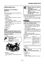
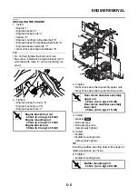
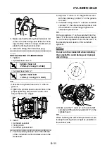
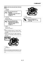
d. Make sure that the timing chain tensioner rod
comes out of the timing chain tensioner hous-
ing smoothly. If there is rough movement, re-
place the timing chain tensioner.
e. Install the timing chain tensioner plug.
▲▲▲
▲
▲ ▲▲▲
▲
▲ ▲▲▲
▲
▲ ▲▲▲
▲
▲ ▲▲▲
▲
▲ ▲▲▲
▲
▲▲▲
EAS2DM1035
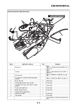
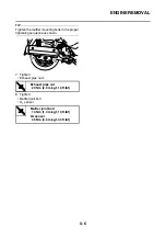
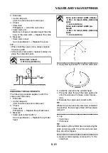
INSTALLING THE CYLINDER HEAD
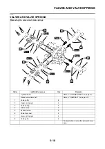
1. Tighten:
• Cylinder head nuts “1”
• Cylinder head bolts “2”
TIP
• Lubricate the cylinder head nuts “1” with en-
gine oil.
• Tighten the cylinder head nuts and bolts in the
proper tightening sequence as shown and
torque them in two stages.
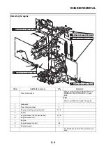
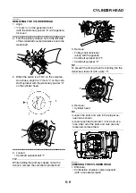
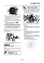
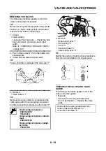
2. Install:
• Camshaft sprocket
• Timing chain
• Camshaft sprocket bolt
▼▼▼
▼
▼ ▼▼▼
▼
▼ ▼▼▼
▼
▼ ▼▼▼
▼
▼ ▼▼▼
▼
▼ ▼▼▼
▼
▼▼▼
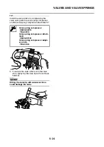
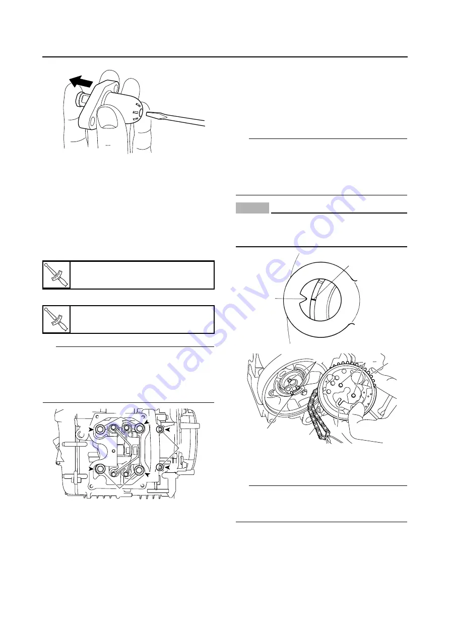
a. Turn the primary sheave nut on the left side
of the crankshaft counterclockwise to turn the
crankshaft.
b. Align the “I” mark “a” on the generator rotor
with the stationary pointer “b” on the genera-
tor cover.
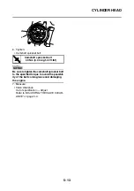
c. Install the timing chain “1” onto the camshaft
sprocket “2”, then the camshaft sprocket onto
the camshaft, and then finger tighten the
camshaft sprocket bolt.
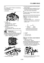
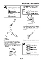
TIP
Fit the projections “c” on the camshaft into the
holes “d” in the camshaft sprocket and fit the pin
“e” on the decompression cam into the slot “f” in
the decompression lever on the camshaft
sprocket.
NOTICE
ECA2DM1030
Do not turn the crankshaft when installing
the camshaft to avoid damage or improper
valve timing.
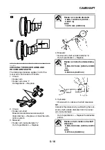
d. Make sure the “I” mark “g” on the camshaft
sprocket with the stationary pointer “h” on the
cylinder head.
TIP
When installing the camshaft sprocket, be sure
to keep the timing chain as tight as possible on
the exhaust side.
T
R
.
.
Cylinder head nut
22 Nm (2.2 m·kgf, 16 ft·lbf)
T
R
.
.
Cylinder head bolt
10 Nm (1.0 m·kgf, 7.2 ft·lbf)
6
4
1
2
5
3
1
1
2
b
a
1
e
f
c
d
2
Содержание MBK XMAX 2014
Страница 1: ...2014 SERVICE MANUAL YP125R YP125RA 2DM F8197 E0 ...
Страница 6: ......
Страница 8: ......
Страница 64: ...TIGHTENING TORQUES 2 17 Muffler tightening sequence 1 2 3 ...
Страница 72: ...LUBRICATION SYSTEM DIAGRAMS 2 25 EAS2DM1116 LUBRICATION SYSTEM DIAGRAMS 1 2 3 4 5 3 ...
Страница 73: ...LUBRICATION SYSTEM DIAGRAMS 2 26 1 Camshaft 2 Crankshaft 3 Oil pump 4 Oil filter 5 Oil strainer ...
Страница 78: ...CABLE ROUTING 2 31 Steering head front view 1 2 3 4 5 6 8 8 A 7 7 ...
Страница 80: ...CABLE ROUTING 2 33 Front brake left side view for YP125R 1 2 2 1 1 2 2 D E A B C ...
Страница 82: ...CABLE ROUTING 2 35 Front brake left side view for YP125RA 2 1 1 2 1 2 2 A B D E C ...
Страница 84: ...CABLE ROUTING 2 37 Engine and rear brake left side and right side view for YP125R B 2 1 2 1 2 A A 3 3 C ...
Страница 86: ...CABLE ROUTING 2 39 Engine and rear brake left side and right side view for YP125RA 1 2 1 2 2 A A B 3 4 3 4 4 ...
Страница 92: ...CABLE ROUTING 2 45 Frame right side view 3 2 4 1 2 3 A B 6 5 3 A B 3 3 2 3 3 A A B A B B 3 ...
Страница 94: ...CABLE ROUTING 2 47 Engine right side view 6 6 6 6 C D C D D C 10 B 9 5 6 1 2 8 3 4 5 6 7 A ...
Страница 98: ...CABLE ROUTING 2 51 Frame left side view C D C D 2 1 E 1 2 D C 6 1 4 5 3 2 1 7 3 2 1 A B ...
Страница 100: ...CABLE ROUTING 2 53 Engine left side view 1 1 1 1 1 2 3 4 5 6 7 8 9 7 7 A B A B A B 1 ...
Страница 102: ...CABLE ROUTING 2 55 Frame top view 7 8 9 10 11 12 13 13 17 19 19 A D B C 14 C B 1 2 3 4 5 6 14 15 16 18 19 ...
Страница 104: ...CABLE ROUTING 2 57 Engine and frame top view 1 2 4 5 6 7 8 9 10 11 12 13 1 4 5 6 7 8 1 3 10 11 6 8 C 3 11 B A B A 3 ...
Страница 106: ...CABLE ROUTING 2 59 Rear brake right side view 2 2 2 2 2 2 1 1 2 3 A B C 3 ...
Страница 108: ...CABLE ROUTING 2 61 Hydraulic unit for YP125RA 3 2 1 2 3 3 2 2 3 2 2 2 3 3 3 4 4 1 1 4 2 6 B A A 5 1 5 1 5 ...
Страница 110: ...CABLE ROUTING 2 63 ...
Страница 228: ...REAR SHOCK ABSORBER ASSEMBLIES AND SWINGARM 4 89 ...
Страница 231: ......
Страница 291: ...CRANKSHAFT 5 60 a 1 ...
Страница 292: ...CRANKSHAFT 5 61 ...
Страница 302: ...WATER PUMP 6 9 ...
Страница 313: ......
Страница 329: ...CHARGING SYSTEM 8 16 2 AC magneto 3 Rectifier regulator 12 Battery 13 Main fuse 17 Frame ground ...
Страница 331: ...CHARGING SYSTEM 8 18 ...
Страница 349: ...COOLING SYSTEM 8 36 ...
Страница 391: ...FUEL PUMP SYSTEM 8 78 ...
Страница 400: ...IMMOBILIZER SYSTEM 8 87 a Light on b Light off ...
Страница 401: ...IMMOBILIZER SYSTEM 8 88 ...
Страница 405: ...ABS ANTI LOCK BRAKE SYSTEM for YP125RA 8 92 ...
Страница 439: ...ABS ANTI LOCK BRAKE SYSTEM for YP125RA 8 126 ...
Страница 464: ...ELECTRICAL COMPONENTS 8 151 ...
Страница 476: ......
Страница 477: ......
Страница 478: ......