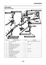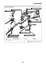
HANDLEBAR
4-71
EAS22860
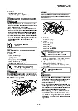
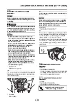
REMOVING THE HANDLEBAR
1. Stand the vehicle on a level surface.
WARNING
EWA13120
Securely support the vehicle so that there is
no danger of it falling over.
2. Remove:
• Handlebar grip “1”
TIP
Blow compressed air between the handlebar
and the handlebar grip, and gradually push the
grip off the handlebar.
EAS22880
CHECKING THE HANDLEBAR
1. Check:
• Handlebar
Bends/cracks/damage
→
Replace.
WARNING
EWA13690
Do not attempt to straighten a bent handle-
bar as this may dangerously weaken it.
EAS22920
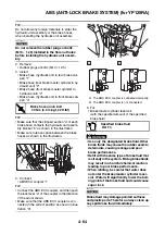
INSTALLING THE HANDLEBAR
1. Stand the vehicle on a level surface.
WARNING
EWA13120
Securely support the vehicle so that there is
no danger of it falling over.
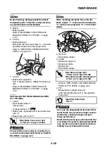
2. Install:
• Handlebar
• Upper handlebar holders
NOTICE
ECA37P1031
First, tighten the front bolt on each handle-
bar holder, then the rear bolt.
TIP
The upper handlebar holders should be installed
with the arrow marks “a” facing forward “A”.
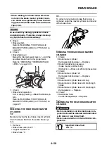
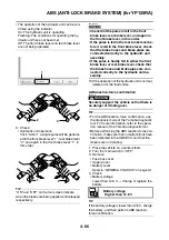
3. Install:
• Left handlebar switch “1”
TIP
Align the projection “a” on the left handlebar
switch with the hole “b” in the handlebar.
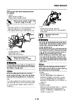
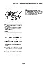
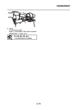
4. Install:
• Handlebar grip “1”
• Left grip end “2”
▼▼▼
▼
▼ ▼▼▼
▼
▼ ▼▼▼
▼
▼ ▼▼▼
▼
▼ ▼▼▼
▼
▼ ▼▼▼
▼
▼▼▼
a. Apply a thin coat of a rubber adhesive to the
left end of the handlebar.
b. Slide the handlebar grip over the left end of
the handlebar.
TIP
Make sure that the distance “a” between the end
of the left handlebar switch and the end of the
handlebar grip is 0–2.5 mm (0–0.10 in).
c. Wipe off any excess rubber adhesive with a
clean rag.
T
R
.
.
Upper handlebar holder bolt
23 Nm (2.3 m·kgf, 17 ft·lbf)
T
R
.
.
Left handlebar switch screw
2.3 Nm (0.23 m·kgf, 1.7 ft·lbf)
T
R
.
.
Left grip end bolt
12 Nm (1.2 m·kgf, 8.7 ft·lbf)
b
a
1
Содержание MBK XMAX 2014
Страница 1: ...2014 SERVICE MANUAL YP125R YP125RA 2DM F8197 E0 ...
Страница 6: ......
Страница 8: ......
Страница 64: ...TIGHTENING TORQUES 2 17 Muffler tightening sequence 1 2 3 ...
Страница 72: ...LUBRICATION SYSTEM DIAGRAMS 2 25 EAS2DM1116 LUBRICATION SYSTEM DIAGRAMS 1 2 3 4 5 3 ...
Страница 73: ...LUBRICATION SYSTEM DIAGRAMS 2 26 1 Camshaft 2 Crankshaft 3 Oil pump 4 Oil filter 5 Oil strainer ...
Страница 78: ...CABLE ROUTING 2 31 Steering head front view 1 2 3 4 5 6 8 8 A 7 7 ...
Страница 80: ...CABLE ROUTING 2 33 Front brake left side view for YP125R 1 2 2 1 1 2 2 D E A B C ...
Страница 82: ...CABLE ROUTING 2 35 Front brake left side view for YP125RA 2 1 1 2 1 2 2 A B D E C ...
Страница 84: ...CABLE ROUTING 2 37 Engine and rear brake left side and right side view for YP125R B 2 1 2 1 2 A A 3 3 C ...
Страница 86: ...CABLE ROUTING 2 39 Engine and rear brake left side and right side view for YP125RA 1 2 1 2 2 A A B 3 4 3 4 4 ...
Страница 92: ...CABLE ROUTING 2 45 Frame right side view 3 2 4 1 2 3 A B 6 5 3 A B 3 3 2 3 3 A A B A B B 3 ...
Страница 94: ...CABLE ROUTING 2 47 Engine right side view 6 6 6 6 C D C D D C 10 B 9 5 6 1 2 8 3 4 5 6 7 A ...
Страница 98: ...CABLE ROUTING 2 51 Frame left side view C D C D 2 1 E 1 2 D C 6 1 4 5 3 2 1 7 3 2 1 A B ...
Страница 100: ...CABLE ROUTING 2 53 Engine left side view 1 1 1 1 1 2 3 4 5 6 7 8 9 7 7 A B A B A B 1 ...
Страница 102: ...CABLE ROUTING 2 55 Frame top view 7 8 9 10 11 12 13 13 17 19 19 A D B C 14 C B 1 2 3 4 5 6 14 15 16 18 19 ...
Страница 104: ...CABLE ROUTING 2 57 Engine and frame top view 1 2 4 5 6 7 8 9 10 11 12 13 1 4 5 6 7 8 1 3 10 11 6 8 C 3 11 B A B A 3 ...
Страница 106: ...CABLE ROUTING 2 59 Rear brake right side view 2 2 2 2 2 2 1 1 2 3 A B C 3 ...
Страница 108: ...CABLE ROUTING 2 61 Hydraulic unit for YP125RA 3 2 1 2 3 3 2 2 3 2 2 2 3 3 3 4 4 1 1 4 2 6 B A A 5 1 5 1 5 ...
Страница 110: ...CABLE ROUTING 2 63 ...
Страница 228: ...REAR SHOCK ABSORBER ASSEMBLIES AND SWINGARM 4 89 ...
Страница 231: ......
Страница 291: ...CRANKSHAFT 5 60 a 1 ...
Страница 292: ...CRANKSHAFT 5 61 ...
Страница 302: ...WATER PUMP 6 9 ...
Страница 313: ......
Страница 329: ...CHARGING SYSTEM 8 16 2 AC magneto 3 Rectifier regulator 12 Battery 13 Main fuse 17 Frame ground ...
Страница 331: ...CHARGING SYSTEM 8 18 ...
Страница 349: ...COOLING SYSTEM 8 36 ...
Страница 391: ...FUEL PUMP SYSTEM 8 78 ...
Страница 400: ...IMMOBILIZER SYSTEM 8 87 a Light on b Light off ...
Страница 401: ...IMMOBILIZER SYSTEM 8 88 ...
Страница 405: ...ABS ANTI LOCK BRAKE SYSTEM for YP125RA 8 92 ...
Страница 439: ...ABS ANTI LOCK BRAKE SYSTEM for YP125RA 8 126 ...
Страница 464: ...ELECTRICAL COMPONENTS 8 151 ...
Страница 476: ......
Страница 477: ......
Страница 478: ......

