96
Chapter 7—Input Channels
DM2000 Version 2—Owner’s Manual
Pan Pages
Pan settings can be viewed and set on the Pan pages. If the Auto PAN/SURROUND Display
preference is on, these pages appear automatically when a control in the SELECTED
CHANNEL PAN/SURROUND section is operated.
1
Use the SELECTED CHANNEL PAN/SURROUND [DISPLAY] button to select
the Input Channel Pan pages.
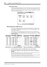
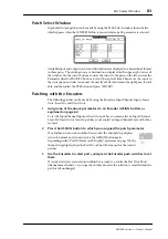
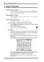
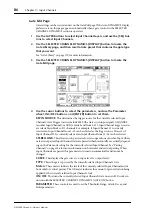
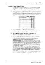
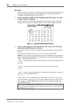
The Pan parameters for the 96 Input Channels are arranged into four pages. The Input
Channel 1–24 Pan page is shown below. The layout of the other three pages is the same.
2
Use the cursor buttons to select the Pan controls, and use the Parameter
wheel and INC/DEC buttons to set them.
Pan parameters can also be selected by using the Input Channel Layer buttons and [SEL]
buttons.
The currently selected Pan control can be set to center by pressing [ENTER].
MODE:
There are three Pan modes that determine how horizontally and vertically paired
Input Channels are panned: Individual, Gang, and Inverse Gang. This is a global setting that
applies to all paired Input Channels.
In individual mode, paired Input Channel pan controls operate independently.
In Gang mode, paired Input Channel pan controls operate in unison.
In Inverse Gang mode, paired Input Channel pan controls operate in unison but
move in opposite directions.
Aux Send Pan controls can be linked to Input Channel Pan controls so that operating an
Input Channel Pan control also operates the corresponding Aux Send Pan control, and vice
versa (see page 116). While linked, the Pan mode can be set on the Aux Pan page or the
Input Channel Pan page.
Note: While the PAN/SURROUND [LINK] button is turned on, the Pan mode is automati-
cally set to Individual. When the Pan mode is switched from Gang mode to Inverse Gang mode,
the [LINK] button is turned off.

