background image

88

Chapter 7—Input Channels

DM2000 Version 2—Owner’s Manual

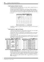
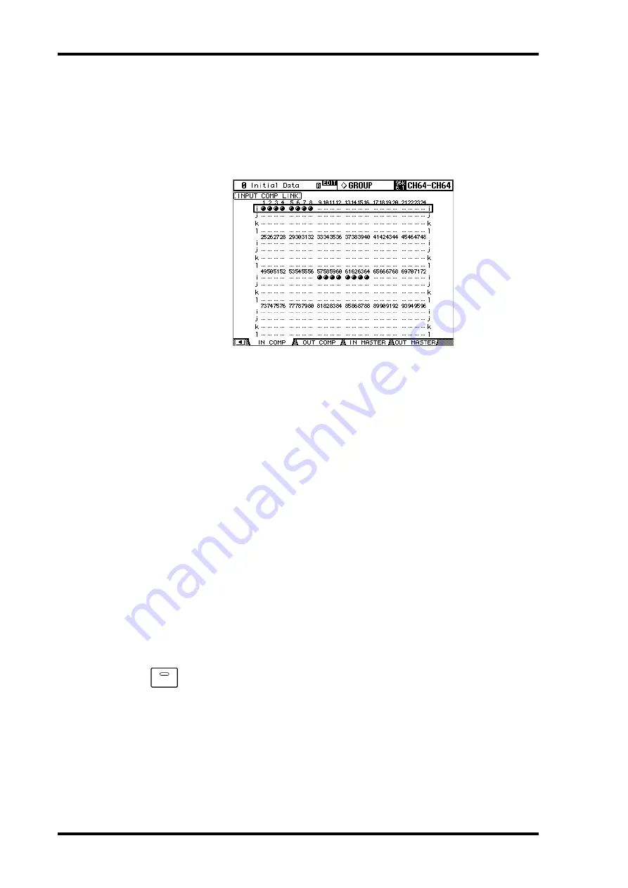
Grouping Input Channel Compressors

Input Channel Compressors can be grouped, allowing you to control the compression of 
several Input Channels simultaneously by operating any Compressor control in the group. 
There are four Input Channel Compressor groups: i, j, k, and l.

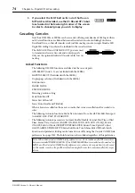
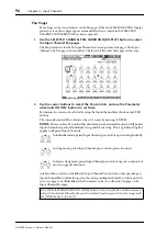
1

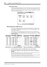
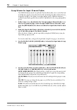
Use the DISPLAY ACCESS [GROUP] button to locate the Input Comp Link 
page.

2

Use the LAYER buttons to select the Input Channel Layers.

The corresponding group row is selected as each Input Channel Layer is selected.

3

Use the Up/Down cursor buttons to select Comp groups i–l.

The selected group is highlighted by a flashing cursor box.

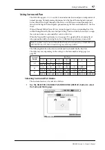
4

Use the [SEL] buttons to add and remove Input Channels to and from the 
selected group.

The Compressor settings of the first Input Channel added to the group are applied to all 
subsequently added Input Channels.

When an Input Channel is added to a group, its [SEL] button indicator lights up.

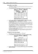
Delaying Input Channels

Each Input Channel features a Delay function. See “Delaying Channel Signals” on page 141 
for more information.

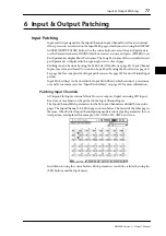
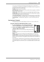
Muting Input Channels (ON/OFF)

Input Channels can be muted as follows.

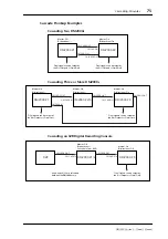
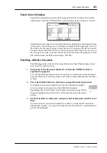
1

Use the LAYER buttons to select the Input Channel Layers.

2

Use the [ON] buttons to mute the Input Channels on the selected Layer.

The [ON] button indicators of channels that are on are lit.

ON

Содержание DM 2000 Version 2

Страница 1: ...EN Owner s Manual Owner s Manual Keep This Manual For Future Reference Keep This Manual For Future Reference ...

Страница 2: ...inate the problem by using one of the following measures Relocate either this product or the device that is being affected by the interference Utilize power outlets that are on different branch circuit breaker or fuse circuits or install AC line filter s In the case of radio or TV interference relocate reorient the antenna If the antenna lead in is 300 ohm ribbon lead change the lead in to coaxial...

Страница 3: ...er switch of the unit as soon as possible and unplug the power cable plug from the electrical outlet If there is a possibility of lightning do not touch the power cable plug if it is still connected Doing so may be an electrical shock hazard Use only the included power cord for this unit Using other types may be a fire and electrical shock hazard The DM2000 has six rear panel slots for installing ...

Страница 4: ... outlet Leaving it connected is a potential fire hazard Theinsideof theunitshouldbecleanedperiodically Dustaccumulationinsidetheunitmaycause malfunction and is a potential fire hazard Consult your dealer for information about cleaning To prevent electrical shock when cleaning the unit remove the power plug from theAC outlet Do not apply oil grease or contact cleaner to the faders Doing so may caus...

Страница 5: ...SmartMedia can be protected against inadvertent overwriting by attaching a write protect sticker supplied with SmartMedia Interference The DM2000 uses high frequency digital circuits that may cause interference on radio and television equipment located nearby If interference is a problem relocate the affected equipment Using a mobile telephone near the unit may induce noise In this case use the te...

Страница 6: ... Each chapter of this manual discusses a specific section or function of the DM2000 The Input and Output Channels are explained in the following chapters Input Channels Bus Outs Aux Sends Matrix Sends and Stereo Out Where possible these chapters have been organized in order of signal flow from input through to output Functions such as EQ and Delay are common to all channels Rather than repeat the ...

Страница 7: ...eFadergroup channels simultaneously while maintaining the relative level balance of each channel page 92 The Mute Group Master function enables you to mute all channels in a Mute group simul taneously page 90 Theon off statusof theFollowPanbuttonisreflectedinthepanandSurroundPansettings page 93 Aux Sends You can exclude channels from Aux Sends Mix Minus page 117 You can copy the channel fader posi...

Страница 8: ...Automix You can insert the current mix parameters in a region specified in the Automix data page 203 Touching the faders can punch parameter values in and out if the corresponding OVER WRITE button is set to on page 194 Some parameters related to timecode synchronization have been added page 278 Remote Control TheJoystickorthecontrolsintheSELECTEDCHANNELsectionenableyoutocontrolPro Tools Surround ...

Страница 9: ...CONFORMITY PROCEDURE Responsible Party Yamaha Corporation of America Address 6600 Orangethorpe Ave Buena Park Calif 90620 Telephone 714 522 9011 Type of Equipment Digital Production Console Model Name DM2000 This device complies with Part 15 of the FCC Rules Operation is subject to the following two conditions 1 this device may not cause harmful interference and 2 this device must accept any inter...

Страница 10: ...Channels 59 Selecting Fader Modes 60 Selecting Encoder Modes 61 Assigning Parameters to the ENCODER MODE Assign Buttons 62 4 Analog I O the AD Input Section 64 AD Input Section 64 Stereo Out 65 Control Room Monitor Outs 65 Studio Monitor Outs 65 Omni Outs 65 2TR Analog INs 65 5 Digital I O Cascading 66 Wordclocks 66 2TR Digital Outs 68 2TR Digital Ins 69 2TR In Out Sampling Rate Conversion 69 Slot...

Страница 11: ... 102 Soloing Input Channels 102 Direct Outs 102 Pairing Input Channels 102 Viewing Input Channel Settings 102 Copying Input Channel Settings 102 Naming Input Channels 102 Using the MS Stereo Microphone 103 8 Stereo Out 104 Stereo Out Connectors 104 Patching the Stereo Out to Outputs 104 Routing Input Channels to the Stereo Out 104 Sending Bus Outs to the Stereo Out 104 Metering the Stereo Out 104 ...

Страница 12: ...to Outputs 110 Setting the Aux Send Mode 110 Pre Fader or Post Fader Aux Sends 111 Setting Aux Send Levels 111 Muting Aux Sends ON OFF 112 Aux Send Pages 112 Viewing Aux Send Settings 114 Panning Aux Sends 116 Excluding Certain Channels from Aux Sends Mix Minus 117 Copying Channel Fader Positions to Aux Sends 118 Metering Aux Send Masters 118 Monitoring Aux Send Masters 118 Attenuating Aux Send Ma...

Страница 13: ...ancing Matrix Send Masters 126 Delaying Matrix Send Masters 126 Soloing Matrix Sends 126 Inserting GEQs 126 Viewing Matrix Send Master Settings 126 Copying Matrix Send Master Settings 126 Naming Matrix Send Masters 126 12 Common Channel Functions 127 Metering 127 Attenuating Signals 130 Using EQ 131 Grouping Output Channel EQs 135 Using Inserts 135 Compressing Channels 137 Grouping Output Channel ...

Страница 14: ...EQs 183 Editing the Graphic EQ Using the Channel Faders 184 16 Scene Memories 185 About Scene Memories 185 Auto Scene Memory Update 186 Storing Recalling Scenes with the SCENE MEMORY Buttons 187 Using the Scene Memory Page 188 Fading Scenes 189 Recalling Scenes Safely 190 Sorting Scenes 191 Copying and Pasting a Scene Global Paste 191 17 Automix 193 About Automix 193 What s Recorded in an Automix ...

Страница 15: ...annels 240 Setting Channel Levels 240 Muting Channels 241 Panning Channels 241 Soloing Channels 241 Assigning Send Destinations 242 Configuring Sends as Pre or Post 242 Setting Send Levels 243 Muting Sends 243 Panning Sends 243 Flip Mode 243 Assigning Inserts Plug ins 244 Editing Plug ins 245 Bypassing Individual Plug ins 246 Bypassing all Plug ins 246 Resetting Faders Sends Panpots Plug ins 247 N...

Страница 16: ...get List 302 User Defined Remote Layer Initial Bank Settings 306 Effects Parameters 310 Effects and tempo synchronization 331 Preset EQ Parameters 332 Preset Gate Parameters fs 44 1 kHz 333 Preset Compressor Parameters fs 44 1 kHz 334 Dynamics Parameters 336 Appendix B Specifications 341 General Spec 341 Libraries 346 Analog Input Spec 347 Analog Output Spec 347 Digital Input Spec 348 Digital Outp...

Страница 17: ...tereo Matrix Sends 22 x 8 matrix Stereo Out Channels can be named for easy identification Channel library with 127 user memories Copy and paste channel settings I O Architecture 24 analog mic line inputs on balanced XLRs and phone jacks plus 48 V phantom 24 analog inserts on individual in out phone jacks 48inputs 48outputsviasixmini YGDAIslotsandoptionalI Ocards whichofferavariety of analog and di...

Страница 18: ...s library with 61 presets 67 user memories presets 53 61 are used for optional Add On Effects Optional Add On Effect package includes effects that featuring new algorithms Multichannel effects for surround sound processing Joystick control of early reflections and reverb with the Reverb 5 1 effect Optional Waves 56K effects plug in card User defined plug ins for external effects control via MIDI w...

Страница 19: ...ERIAL TO HOST port USB and SERIAL offer multiport operation Scene recall mix parameter control Bulk Dump MTC and MIDI Clock for Automix syn chronization MMC for external machine control Control Surface 25 touch sensitive 100 mm motorized faders touch sense used to select channels or punch faders in out during Automix recording Use the faders to set channel levels or Aux Matrix Send levels Use the ...

Страница 20: ... 0 10 0 10 STEREO SURROUND 3 LOCATE MEMORY LOCATOR 1 2 3 4 5 6 7 8 ONLINE AUDITION LOOP MASTER PRE POST ROLL BACK IN OUT MTR END QUICK PUNCH REHEARSAL SET RETURN TO ZERO 70 60 50 40 30 20 15 10 5 0 50 40 30 20 15 10 10 5 0 5 70 60 50 40 30 20 15 10 5 0 50 40 30 20 15 10 10 5 0 5 70 60 50 40 30 20 15 10 5 0 50 40 30 20 15 10 10 5 0 5 70 60 50 40 30 20 15 10 5 0 50 40 30 20 15 10 10 5 0 5 70 60 50 4...

Страница 21: ... edit Input and Output Channel parameters Their exact operation depends on the currently selected Encoder mode and Layer There are two preset Encoder modes Pan and Aux Mtrx and four assignable modes with over 50 parameters to choose from See Selecting Encoder Modes on page 61 for more information The Encoders feature push switches that are used to punch the parameter cur rently assigned to the Enc...

Страница 22: ...the currently selected Fader mode and Layer See Selecting Fader Modes on page 60 for more informa tion Faders can be grouped for simultaneous operation See Grouping Input Channel Faders on page 91 and Grouping Output Channel Faders on page 146 for more informa tion Faders can also be used to select Input and Output Channels See Auto Channel Select Touch Sense Select on page 60 for more information...

Страница 23: ...te Layer See About Remote Layers on page 253 for more information A ENCODER MODE DISPLAY button This button is used to select the Encoder ModeAssign page See Selecting Encoder Modes on page 61 for more information B PAN button This button is used to select the Pan Encoder mode Its indicator lights up when this mode is selected In this mode the Encoders function as Pan controls when an Input Channe...

Страница 24: ...lected See Selecting Fader Modes on page 60 for more information DISPLAY ACCESS A DATA button This button is used to select the Save Load and File pages which are used to save and load DM2000 data to SmartMedia See Saving DM2000 Data to SmartMedia on page 271 for more information B DIO button This button is used to select the following pages Word Clock Select Dither Cascade In Cascade Out Sampling...

Страница 25: ... button This button is used to select the Input and Output Pair pages See Pairing Channels on page 144 for more information J GROUP button This button is used to select the following pages Fader group Mute group Output Fader group Output Mute group Input Equalizer Link Output Equalizer Link Input Comp Link Output Comp Link Input Fader Group Master and Output Fader Group Master K INPUT PATCH button...

Страница 26: ... the corresponding EFFECTS PLUG INS 1 8 but ton indicator flashes If it s a Y56K that is inserted the PLUG INS button indicator also flashes If it s an internal effects processor the INTERNAL EFFECTS button indicator flashes A warning message appears if there s nothing inserted in the currently selected channel See Editing Effects on page 177 and Editing Plug Ins on page 181 for more information F...

Страница 27: ...ing In Out Individual Parameters on page 207 for more information Display Section A Display This 320 x 240 dot display with fluorescent backlight displays pages information on the currently selected Scene and channel the sampling rate and more See About the Display on page 52 for more information B Contrast control This control is used to adjust the contrast of the display C F1 F4 buttons These bu...

Страница 28: ...ssed See Routing Input Channels on page 93 for more infor mation D DIRECT button This button is used to route the currently selected Input Channel to its Direct Out Its indi cator lights up when it s pressed See Routing Input Channels on page 93 for more infor mation ROUTING 1 2 3 4 5 6 7 8 STEREO FOLLOW PAN DIRECT GATE ON COMP ON GATE COMP RANGE RATIO ATTACK ATTACK DECAY RELEASE THRESHOLD THRESHO...

Страница 29: ...lay pages See Delaying Channel Signals on page 141 for more information B ON button This button is used to turn on and off the Delay of the currently selected channel Its indi cator lights up when the Delay function is on See Delaying Channel Signals on page 141 for more information C TIME control This control is used to set the delay time of the currently selected channel s Delay function See Del...

Страница 30: ...y the BANK button If the currently selected channel is an Input Channel they control Aux Send levels If it s a Bus Out Aux Send or the Stereo Out they control Matrix Send levels See Setting Aux Send Levels on page 111 and Setting Matrix Send Levels on page 121 for more information E ON buttons These buttons are used to mute the Aux Matrix Sends currently selected by the BANK button The button indi...

Страница 31: ...or more information F GATE COMP indicators These indicators show whether the rotary controls are set to control either a Gate or a Com pressor The GATE indicator lights up when they re set to control a Gate the COMP indi cator when they re set to control a Compressor See Gating Input Channels on page 85 and Compressing Channels on page 137 for more information PAN SURROUND A PAN SURROUND DISPLAY b...

Страница 32: ...When turned off the Joystick does not control surround pan In Stereo mode it controls the currently selected Input Channel s pan position If the PAN control and the Joystick are linked i e the LINK button indicator is lit Grab is turned off if the PAN control is adjusted If the Joy stick is set to control effects i e the EFFECT button indicator is lit this button is dis abled G EFFECT button This ...

Страница 33: ... The current setting is shown by the FREQUENCY Q indicators The rotary controls are used to set the frequency or Q as selected by the push switches See Using EQ on page 131 for more information F EQ GAIN controls These controls are used to set the gain of each EQ band See Using EQ on page 131 for more information G EQ displays Normally these displays show the frequency of each band When the GAIN i...

Страница 34: ...ns on page 199 for more information B SEL button The Stereo Out SEL button is used exclusively to select the Stereo Out for editing with the SELECTED CHANNEL section Its indicator lights up when the Stereo Out is selected Each time it s pressed the selection toggles between the Stereo Out s left and right channels See Selecting Channels on page 59 for more infor mation It can also be used to add a...

Страница 35: ... the target machine DAW MMC or P2 See Arming Machine Tracks on page 261 for more information E MASTER button This button is used to select Master or MTR machines for track arming Its indicator lights up when Master is selected and is off when MTR is selected See About Machine Control MMC P2 on page 256 for more information SCENE MEMORY A SCENE MEMORY DISPLAY button This button is used to select th...

Страница 36: ...e ENABLED DISABLED button on the Automix Main page See Automix Main Page on page 194 C REC button This button is used withAutomix recording It works in unison with the REC button on the Automix Main page See REC on page 197 for more information D ABORT UNDO button This button is used to abort Automix recording or playback It works in unison with the ABORT button on theAutomix Main page See ABORT o...

Страница 37: ...emote Layers on page 253 for more information LOCATOR A LOCATOR DISPLAY button This button is used to select the Locate Memory and Machine Configuration pages See Setting the Locate Memories Pre roll Post roll Roll back on page 260 and Configur ing Machines on page 256 respectively for more information B AUDITION button This button is used to turn on and off the Audition function on the target mac...

Страница 38: ...te commands to the target machine DAW MMC or P2 in order to locate the Locate memory points Their indicators light up momentarily when they re pressed See Using the Locator on page 258 for more information J RETURN TO ZERO button Pressing this button transmits a Locate command to the target machine DAW MMC or P2 in order to locate the Return to Zero point Its indicator lights up momentarily when i...

Страница 39: ... 257 C STOP button This button stops the target machine DAW MMC or P2 Its indicator lights up momen tarily when it s pressed See Transport Buttons on page 257 D PLAY button This button starts playback on the target machine DAW MMC or P2 Its indicator lights up while playback is in progress See Transport Buttons on page 257 E REC button This button is used in conjunction with the PLAY button to sta...

Страница 40: ...eters such as EQ ON OFF and to enter characters when titling Scenes Effects and so on When a Pan control is selected on a Pan display page pressing this button resets the pan position to center For certain parameters the ENTER button supports double clicking i e two quick presses K Parameter wheel The Parameter wheel is used to edit parameter values scroll through Scene and library lists and to po...

Страница 41: ... set the level of the PHONES See Control Room Monitoring on page 158 for more information D PHONES jack This stereo TRS phone jack outputs the Control room signal for monitoring via a pair of stereo headphones E Talkback mic This built in microphone is used for talkback See Using Talkback Slate on page 163 for more information F TALKBACK LEVEL control This control is used to set the level of the b...

Страница 42: ...signal source Its indicator lights up when this source is selected See Studio Monitoring on page 159 for more information E AUX 12 button This button selectsAux Send 12 as the Studio Monitor signal source Its indicator lights up when this source is selected See Studio Monitoring on page 159 for more information SOLO A SOLO indicator This indicator flashes when one or more Channels are soloed indic...

Страница 43: ...toring on page 158 for more information G STEREO ASSIGN 1 button This button is used to select the assigned Output Channel as the Control Room Monitor signal source Its indicator lights up when this source is selected See Control Room Setup on page 159 for more information H STEREO ASSIGN 2 button This button is used to select the assigned Output Channel as the Control Room Monitor signal source I...

Страница 44: ...uted through to the LARGE CONTROL ROOM MONITOR OUTs and when it s on indicator on the signal is routed through to the SMALL CONTROL ROOM MONITOR OUTs See Control Room Monitoring on page 158 for more information P CONTROL ROOM LEVEL control This control is used to adjust the level of the Control Room Monitor signal See Control Room Monitoring on page 158 for more information TALKBACK A SLATE button...

Страница 45: ...Rear Panel 45 DM2000 Version 2 Owner s Manual Rear Panel AD Input Section p 46 SLOT Section p 50 Analog Master I O Section p 46 OMNI OUT Section p 47 Digital I O Control Section p 48 Power Section p 50 ...

Страница 46: ...SERT IN OUT 4dB BAL connectors Thesebalanced1 4 inchTRSphonejacksareusedtoinsert external signal processors etc into AD Inputs 1 through 24 They are wired sleeve ground ring cold tip hot The nominal signal level of both jacks is 4 dB Inserts can be turned on and off individually by using the INSERT ON OFF switches See AD Input Section on page 64 for more information Analog Master I O Section A STU...

Страница 47: ... pressing the CONTROL ROOM 2TR A1 button In addition this input can be patched to Input Channels or Insert Ins See 2TR Analog INs on page 65 F STEREO OUT 10 dBV UNBAL These unbalanced phono connectors nominal output level 10 dBV output the analog Stereo Out signal and are typically connected to the stereo inputs of a 2 track recorder See Stereo Out Connectors on page 104 G 2TR IN ANALOG 2 10 dBV U...

Страница 48: ...rdclock signal at half the clock rate of the DM2000 when using 88 2 kHz or 96 kHz See Wordclock Connections on page 66 for more information G WORD CLOCK OUT 1 connector This BNC connector outputs a wordclock signal at the same clock rate as the DM2000 See Wordclock Connections on page 66 for more information H WORD CLOCK 75Ω ON OFF termination switch This switch applies 75Ω termination to the WORD...

Страница 49: ...udio signals can be converted by the internal sampling rate converters See 2TR Digital Ins on page 69 for more information N METER port This 15 pin D sub connector is for connecting the optional MB2000 Peak Meter Bridge O CONTROL port This 25 pin D sub connector provides access to the GPI General Purpose Interface through which external equipment can be triggered when specified DM2000 faders or US...

Страница 50: ...thod for eliminating hum interference and other noise C AC IN connector This connector is used to connect the DM2000 to anAC outlet via the supplied power cord See Connecting the Power Cord on page 51 for more information D Cooling fan The cooling fan expels air out through this outlet If the airflow is restricted the DM2000 may overheat so make sure this outlet is not blocked SLOT Section A SLOT ...

Страница 51: ...el Turning On Off the DM2000 To prevent loud clicks and thumps in your speakers turn on your audio equipment in the following order reverse this order when turn ing off sound sources multitrack and master recorders DM2000 monitoring power amplifiers 1 To turn on the DM2000 press the POWER switch The startup page appears for a while and then the last selected display page appears 2 To turn off the ...

Страница 52: ...elected channel TheInputorOutputChannelcurrentlyselectedbythe SEL buttons is indicated here See Selecting Channels on page 59 The first four characters are the Channel ID e g CH1 CH96 BUS1 BUS8 AUX1 AUX9 AX10 AX12 MT1L MT4R ST L ST R The second four are the channel s Short name See Naming Channels on page 156 Channel name Depending on the currently selected page this is the Long name of either the...

Страница 53: ...rameter for the cur rently selected channel is selected automatically when channels on different Layers are selected For example if the Input Channel 1 24 Attenuator page is currently selected and then you select say Input Channel 25 by using the LAYER 25 48 button and SEL but ton 1 the Input Channel 25 48 Attenuator page is selected automatically The currently selected page in a group and the par...

Страница 54: ...certain functions the DM2000 prompts you for confirmation before executing them as shown here PressYES to execute the function or press NO to can cel If no action is taken for awhile the confirmation window closes automatically and the function is not executed Title Edit Window The Title Edit window is used to enter titles for Scene and library memories automixes and so on Depending on the item be...

Страница 55: ...border of the currently selected channel s channel strip display lights up like this Fader Touch Sense When fader knobs are touched the corresponding Touch Sense indica tors light up like this Routing Indicators These indicators show to which Output Channels an Input Channel is being routed 1 through 8 being the Bus Outs S being the Stereo Out and D the Direct Out EQ Insert Delay Comp Gate Indicat...

Страница 56: ...On Off EQ Type Gate On Off Comp On Off Aux Send Pre Post Scene Fade Time Parameters Other position Hard right Center indicates at center Hard left indicates center position Other position Maximum Nominal indicates at nominal Minimum indicates nominal position Other position Maximum Nominal indicates at nominal Minimum 96 dB indicates nominal position Other position Maximum Nominal indicates at nom...

Страница 57: ...L button After about one second the channel s Short name Long name and Channel ID are dis played as shown below All other items in the displays are turned off while the SEL button is held down 2 Release the SEL button when you ve finished The channel strip displays return to normal Channel Faders and Encoders When you operate the channel faders the corresponding levels are indicated in four digits...

Страница 58: ...ends on the currently selected Fader mode and Encoder mode respectively See Selecting Fader Modes on page 60 and Selecting Encoder Modes on page 61 for more information Layers Channel Strips 1 8 9 16 17 20 21 24 1 24 Input Channels 1 24 25 48 Input Channels 25 48 49 72 Input Channels 49 72 73 96 Input Channels 73 96 MASTER Bus Out masters 1 8 Aux Send masters 1 12 Matrix Send masters 1 4 REMOTE 1 ...

Страница 59: ...tor lights up The SEL button indicator of the other channel flashes Vertical and horizontal Input and Output channel partners can also be selected by using the SELECTED CHANNEL PAN SURROUND L and R buttons which can also be used to select left and right channels when a Matrix Send or the Stereo Out is selected If the currently displayed page contains a relevant parameter when a channel s SEL but t...

Страница 60: ...uttons to select channels only during Automix recording or in Automix record ready mode While the Fader Touch Sense SELECT preference is on see page 276 channels can be selected simply by touching the fader knobs Selecting Fader Modes The exact function of each fader depends on the selected Layer and Fader mode 1 Select a Layer as explained on page 58 2 Use the FADER MODE buttons to select a Fader...

Страница 61: ...by the channel strip displays See Channel Strip Displays on page 55 for more information Layer Encoder Mode Encoder 1 8 9 16 17 20 21 24 1 24 Pan CH 1 24 pan Aux Mtrx CH 1 24 Aux Send level Assign 1 4 CH 1 24 assigned parameter1 1 When Alt Layer is assigned the Encoders enable you to control a parameter that is assigned to the cor responding channel fader in the partner layer A partner layer would...

Страница 62: ...ppears highlighted in the right hand box 2 Press an ASSIGN button or use the Up Down cursor buttons to select an ASSIGN button 3 Use the Parameter wheel or the INC DEC buttons to select a parameter A parameter is selected when it appears inside the dotted box See the Assignable Encoder Mode Parameter List on page 63 for a complete list of assign able parameters 4 Press the ENTER button to assign y...

Страница 63: ...ow Mid Q EQ Low Mid Q 20 EQ Low Mid F EQ Low Mid Frequency 21 EQ Low Mid G EQ Low Mid Gain 22 EQ High Mid Q EQ High Mid Q 23 EQ High Mid F EQ High Mid Frequency 24 EQ High Mid G EQ High Mid Gain 25 EQ High Q EQ High Q 26 EQ High F EQ High Frequency 27 EQ High G EQ High Gain 28 Gate On Gate on off 29 Gate Threshold Gate Threshold 30 Gate Range Gate Range 31 Gate Attack Gate Attack 32 Gate Decay Gat...

Страница 64: ...um microphones or hot line level signals Gain AD Inputs feature detented rotary gain controls with an input sensitivity of 16 dB to 60 dB or 10 dB to 34 dB when the Pad is on The GAIN controls adjust the gain of the Head Amps allowing you to optimize input signal levels for the best signal to noise performance Ideally the GAIN control should be set so that the signal level is relatively high and i...

Страница 65: ...on on the Control Room Monitor outputs Studio Monitor Outs See page 159 for information on the Studio Monitor outputs Omni Outs The DM2000 features assignable Omni Outs on balanced 1 4 inch TRS phone jacks Omni Outs can be patched to Bus Outs Aux Sends Matrix Sends the Stereo Out Input or Output Channel Insert Outs or Surround Monitor Channels see page 80 In addition Input Channel Direct Outs can ...

Страница 66: ...wn internally generated wordclock If you re connecting other equipment digitally however you must decide which device to use as the wordclock master and which devices to use as slaves The DM2000 can be used as the wordclock master running at either 44 1 kHz 48 kHz 88 2 kHz or 96 kHz or slaved to an external wordclock source External wordclock signals can be received via the Slot Inputs 2TR Digital...

Страница 67: ...CADE IN port as the wordclock source 2TRD1 2TRD2 2TRD3 These buttons select the 2TR Digital Inputs as the wordclock source INT44 1k INT48k INT88 2k INT96k These buttons select the internal wordclock generator as the wordclock source The source select buttons have the following indications A usable wordclock signal is present at this input No wordclock signal is present at this input A wordclock si...

Страница 68: ...ms 2TR Digital Outs The DM2000 features three sets of 2 track digital outputs 2TR OUT DIGITALAES EBU 1andAES EBU 2useXLR 3 32 typeconnectors and output AES EBU format digital audio 2TR OUT DIGITAL COAXIAL 3 uses a phono connector and outputs consumer format IEC 60958 digital audio These outputs can be patched to the Bus Outs Aux Sends Matrix Sends the Stereo Out Input or Output Channel Insert Outs...

Страница 69: ... Monitor page see page 73 2TR In Out Sampling Rate Conversion The DM2000 s 2TR Digital Inputs and Outputs feature sampling rate converters so you can easily connect your legacy 44 1 48 kHz digital audio equipment 1 Use the DISPLAY ACCESS DIO button to locate the Sampling Rate Con verter page 2 Use the cursor buttons to select the parameters and use the Parameter wheel INC DEC buttons or ENTER butt...

Страница 70: ...mat In Out Resolution Sampling Rate Connectors MY8 AD Analog in 8 20 bit 44 1 48 kHz Phone jack balanced x8 MY8 AD241 1 This card is a substitution for a 20 bit MY8 AD card 24 bit 44 1 48 kHz MY4 AD 4 XLR 3 31 type balanced x4 MY8 AD96 8 24 bit 44 1 48 88 2 96 kHz D sub 25 pin MY4 DA Analog out 4 20 bit 44 1 48 kHz XLR 3 32 type balanced x4 MY8 DA96 8 24 bit 44 1 48 88 2 96 kHz D sub 25 pin MY8 AD...

Страница 71: ...er nal connector 4 Secure the card using the attached thumbscrews Do not leave them loose as the card will not be grounded correctly which may cause the DM2000 to malfunction You can check which I O Cards are installed on the Word Clock Select page see page 67 For technical reasons certain card combinations are not supported Before installinganycards checktheYamahawebsite seepage 6 toseewhetheryou...

Страница 72: ...annel I O Card to four In Double Channel mode the even numbered channels are disabled Double Channel mode allows you to record 96 kHz audio to legacy 44 1 48 kHz digital multitrack recorders In Single mode digital audio data is received and transmitted at a sampling rate that is exactly half the cur rent higher sampling rate This is useful for digital MTR recording and playback situations The IN a...

Страница 73: ...ed I O Cards You can copy the currently selected setting to all Dither parameters by double clicking the ENTER button Monitoring Digital Input Channel Status You can monitor the Channel Status of digital audio signals connected to the 2TR Digital Inputs and Slot Inputs as follows 1 Use the DISPLAY ACCESS UTILITY button to locate the Channel Status Mon itor page 2 Use the cursor buttons to select t...

Страница 74: ... Not linked with the 02R96 Solo function FADER MODE ENCODER MODE Metering position setting Peak Hold On Off Meter Fast Fall on off Scene Store Recall and Title Edit When a Scene is recalled on the master console that scene is recalled on all cascaded con soles The following Automix functions Make New Automix Store Recall Title Edit Transport AutoREC REC PLAY STOP ABORT The following Automix parame...

Страница 75: ... Master On Bi directional On DM2000 1 DM2000 2 3 DM2000 4 CASCADE IN CASCADE OUT CASCADE IN CASCADE OUT CASCADE OUT CASCADE IN Master Off Bi directional Final signals can be output by the Slot Outputs or Omni Outs Master Off Bi directional Master On Bi directional On Final signals can be output by the Slot Outputs or Omni Outs 02R DM2000 1 2 DM2000 3 CASCADE IN CASCADE OUT CASCADE IN CASCADE OUT M...

Страница 76: ...he master console When the BI DIRECTIONAL button is off the last DM2000 in the cascade is automatically configured as the master console and it output the final signals CASCADE IN FROM This is used to specify the type of device connected to the CAS CADE IN port either DM2000 or 02R When a DM2000 or 02R96 is connected to the CAS CADE IN port DM2000 is specified automatically CASCADE IN ATTENUATOR T...

Страница 77: ... the Encoders see page 83 See page 286 for a complete list of input patch sources See page 289 for a list of initial input patches Input Patch settings can be stored in the Input Patch library which contains 1 preset mem ory and 32 user memories See Input Patch Library on page 167 for more information Patching Input Channels AD Inputs Slot Inputs internal effects Processor outputs Digital or Analo...

Страница 78: ...UT2 only or Output Channel Insert Outs can be patched to the internal effects processor inputs Input Channels or Insert Ins can be patched to the internal effects processor outputs Inter nal effects processor inputs can be also patched to the internal effects processor outputs OUT1 and OUT2 only The internal effects processor Input Patch parameters are divided between two pages One for Effects Pro...

Страница 79: ...0 for a complete list of output patch sources See page 297 for a list of initial out put patches Output Patch settings can be stored in the Output Patch library which contains 1 preset memory and 32 user memories See Output Patch Library on page 167 for more informa tion Patching Slot Outputs Bus Outs Aux Sends Matrix Sends the Stereo Out Input or Output Channel Insert Outs or Surround Monitor Cha...

Страница 80: ...en an Omni Out is patched to a Direct out see page 81 and that Direct Out is assigned on an Input Channel Routing page the Omni Out patch cannot be changed here Output Channel Inserts Ins AD Inputs Slot Inputs internal effects processor outputs or Digital or Analog 2TR Inputs can be patched to the Output Channel Insert Ins The left and right channels of the Matrix Sends and the Stereo Out can be p...

Страница 81: ...parameters can also be selected by using the SEL buttons Patching the 2TR Digital Outputs Bus Outs Aux Sends Matrix Sends the Stereo Out Input or Output Channel Insert Outs or the Control Room signal can be patched to the 2TR Digital Outputs 2TR Digital Out puts can be patched to Direct Outs on the Direct Out Destination pages see page 81 The left and right channels of each Digital Output can be p...

Страница 82: ...el strip displays when patching with the Encoders See page 300 for a list of the initial Input Port names page 301 for Output Port names 1 Use the DISPLAY ACCESS SETUP button to locate the Input Port or Output Port Name page 2 Use the Parameter wheel or INC DEC buttons to select the ports 3 Use the cursor buttons to select the Long or Short name and then press ENTER When the Title Edit window appe...

Страница 83: ...e by using the Encoders Input Channel Inputs Insert Outs Insert Ins and Direct Outs 1 Assign one of the above parameters to an Encoder ASSIGN button as explained on page 62 To set the Input Channel Input or Direct Out patches you must select an Input Channel Layer For Insert Out or Insert In patches you can select an Input Channel Layer or the Mas ter Layer 2 Press the ASSIGN button to which you a...

Страница 84: ...o set the phase Phase is reversed when the Phase button indicator is lit Phase Pages Phase settings can be viewed and set on the Phase pages If the Auto PHASE INSERT Dis play preference is on these pages appear automatically when you press the Phase button in the SELECTED CHANNEL PHASE INSERT section turning on the button indicator See Auto PHASE INSERT Display on page 274 1 Use the SELECTED CHANN...

Страница 85: ... 1 Use the LAYER buttons to select Input Channel Layers and use the SEL but tons to select Input Channels 2 Use the GATE ON button to turn the currently selected Input Channel s Gate on or off 3 Use the GATE COMP button to set the DYNAMICS controls to GATE GATE indicator lit and use the THRESHOLD RANGE ATTACK DECAY and HOLD controls to set the Gate Preset Name Type Description 1 Gate GATE Gate tem...

Страница 86: ... 12 channels For example if Input Channel 1 is currently selected an Input Channel from 1 12 can be selected as the trigger source However if Input Channel 13 is currently selected an Input Channel from 13 24 can be selected STEREO LINK This allows you to pair Gates for stereo operation even when Input Chan nels are not paired Input Channel Gates are paired either horizontally or vertically depend...

Страница 87: ...Input Channel Layers The corresponding group row is selected as each Input Channel Layer is selected 3 Use the Up Down cursor buttons to select EQ groups a d The selected group is highlighted by a flashing cursor box 4 Use the SEL buttons to add and remove Input Channels to and from the selected group The EQ settings of the first Input Channel added to the group are applied to all subse quently ad...

Страница 88: ...uttons to select Comp groups i l The selected group is highlighted by a flashing cursor box 4 Use the SEL buttons to add and remove Input Channels to and from the selected group The Compressor settings of the first Input Channel added to the group are applied to all subsequently added Input Channels When an Input Channel is added to a group its SEL button indicator lights up Delaying Input Channel...

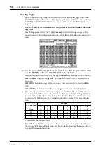
Страница 89: ... select Mute groups I P The selected group is highlighted by a flashing cursor box 4 Use the SEL buttons to add and remove mutes to and from the selected group When an Input Channel is added to a Mute group its SEL button indicator lights up ENABLE These buttons are used to enable and disable the groups INPUT MUTE MASTER When this check box is checked clicking a MASTER MUTE button mutes or unmutes...

Страница 90: ...r the channels in the corre sponding Mute group If the channels are muted by the Mute Master function the corresponding channel ON button indicators flash You can assign the MASTER MUTE button function to one of the USER DEFINED KEYS for convenient operation Setting Input Channel Levels Input Channel levels can be set as follows 1 Use the LAYER buttons to select the Input Channel Layers 2 Press th...

Страница 91: ... Channel is added to a group its SEL button indicator lights up ENABLE These buttons are used to enable and disable the groups INPUT FADER MASTER When this check box is unchecked the Input Channel fader positions link to the fader levels for the channels in the corresponding Fader group When this check box is checked you can set the master level for the corresponding Input Channel Fader group in t...

Страница 92: ...ter column is selected repeatedly pressing the ENTER button turns the Input Fader group on and off You can also make these settings in the Input Fader Group Master page as shown below 3 Use the DISPLAY ACCESS GROUP button to locate the Input Fader Group Master page 4 Use the cursor buttons to select parameters then use the Parameter wheel INC DEC buttons or ENTER button to set the parameters INPUT...

Страница 93: ...annel can be routed to the Bus Outs Stereo Out or its own Direct Out Using the SELECTED CHANNEL ROUTING Controls 1 Use the LAYER buttons to select the Input Channel Layers and use the SEL buttons to select the Input Channels 2 Use the 1 8 STEREO and DIRECT buttons to route the currently selected Input Channel 1 8 ThesebuttonsroutethecurrentlyselectedInputChanneltothe Bus Outs STEREO Thisbuttonrout...

Страница 94: ...ttons ALL STEREO This button assigns all Input Channels that are currently displayed to the Stereo Out ALL BUS This button assigns all Input Channels that are currently displayed to all Bus Outs ALL CLEAR This button clears all routing assignments that are currently displayed The currently selected Surround mode is displayed in the lower left corner When Stereo mode is selected the Bus Out routing...

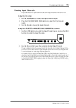
Страница 95: ... 2 Use the Pan control to pan the currently selected Input Channel The pan display indicates the pan position of the currently selected Input Channel When pan is set to center the center two segments light up You can use the L and R buttons to select horizontal or vertical Input Channel partners The LINK button which is enabled only when a Surround mode other than Stereo is selected is used to lin...

Страница 96: ...cted Pan control can be set to center by pressing ENTER MODE There are three Pan modes that determine how horizontally and vertically paired Input Channels are panned Individual Gang and Inverse Gang This is a global setting that applies to all paired Input Channels In individual mode paired Input Channel pan controls operate independently In Gang mode paired Input Channel pan controls operate in ...

Страница 97: ...s on see page 275 signals will be at nominal level when panned hard left or hard right and at 3 dB when the preference is turned off The following table shows how Surround channels are handled by the Bus Outs The table may vary depending on the settings on the Surround Bus Setup page see page 99 Selecting Surround Pan Modes The Surround mode can be selected as follows 1 Use the SELECTED CHANNEL PA...

Страница 98: ... the typical sound image placement and the Surround channel to Bus Out configuration Select the SURR BUS SETUP button then press the ENTER button to display the Sur round Bus Setup page which enables you to change the Surround Channel to Bus Out assignment See Assigning Surround Channels to Buses on page 99 for more information on the Surround Bus Setup page 3 1 Surround 5 1 Surround 6 1 Surround ...

Страница 99: ...channel assignment to the default setting Using the Joystick 1 Use the LAYER buttons to select the Input Channel Layers and use the SEL buttons to select the Input Channels 2 Press the GRAB button to grab the current Joystick position and then use the Joystick to set the surround pan Thisisusedtoturnonandoff JoysticksurroundpancontrolforthecurrentlyselectedInput Channel While Grab is on the Joysti...

Страница 100: ...f the Auto Grab preference is on see page 276 when the Joystick is moved to the current surround pan position the Joystick kicks in as surround pan control and the small square disappears The number of speaker icons and meters around the surround graph depends on the cur rently selected Surround mode The meters indicate Bus Out signal levels You can move the surround pan directly to one of the spe...

Страница 101: ...the eight patterns selectable here determine how the linked surround pan moves by the Parameter wheel and INC DEC buttons Input Channel Surround Pages Surround pan positions can be viewed and set on the Surround pages 1 Use the SELECTED CHANNEL PAN SURROUND DISPLAY button to select the Input Channel Surround pages The Surround parameters for the 96 Input Channels are arranged into four pages The I...

Страница 102: ...ts on page 81 and Routing Input Channels on page 93 for more information Pairing Input Channels Horizontal or vertical Input Channel partners can be paired for stereo operation See Pair ing Channels on page 144 for more information Viewing Input Channel Settings Parameter and fader settings for each Input Channel can be viewed on the View pages See Viewing Channel Parameter Settings on page 150 an...

Страница 103: ...MS microphone with the DM2000 connect the L connector to the input jack of an odd Input Chan nel and connect the R connector to the input jack of the partner channel 2 Use the DISPLAY ACCESS PAIR button to locate the Pair pages 3 Turn on the MS button for the channels to which the MS microphone is con nected The two channels are automatically paired and MS Decoding is turned on With MS Decod ing t...

Страница 104: ... on page 109 for more information Metering the Stereo Out Stereo Out signal levels can be metered on the Meter pages See Metering on page 127 for more information Monitoring the Stereo Out The Stereo Out can be monitored via the LARGE and SMALL CONTROL ROOM MON ITOR OUTs and the PHONES see page 158 or the STUDIO MONITOR OUT see page 159 Attenuating the Stereo Out Stereo Out signals can be attenuat...

Страница 105: ...or lights up when the Stereo Out is on Grouping Master Mutes ON OFF The Stereo Out Mute can be grouped with the Mutes of other Output Channels See Grouping Output Channel Mutes ON OFF on page 149 for more information Setting the Stereo Out Level The Stereo Out level is set by using the STEREO fader which is used exclu sively for this task and is not affected by the Layers or Fader modes Grouping M...

Страница 106: ...Delay See Delaying Channel Signals on page 141 for more information Inserting GEQs Internal GEQs can be inserted into the left and right channels of the Stereo Out See About the GEQs on page 183 for more information Viewing Stereo Out Settings Parameter and fader settings for the Stereo Out can be viewed and set on the View pages See Viewing Channel Parameter Settings on page 150 and Viewing Chann...

Страница 107: ...ts Bus Out signals can be attenuated pre EQ See Attenuating Signals on page 130 for more information EQ ing Bus Outs Each Bus Out features 4 band parametric EQ See Using EQ on page 131 for more infor mation Grouping Master EQs Bus Out EQs can be grouped with the EQs of other Output Channels See Grouping Out put Channel EQs on page 135 for more information Bus Out Inserts Internal effects processor...

Страница 108: ...o set the Bus Out levels Refer to the legend on the right side of the faders when setting Bus Out levels Grouping Master Faders Bus Out faders can be grouped with the faders of other Output Channels See Grouping Output Channel Faders on page 146 for more information Sending Bus Outs to Matrix Sends Bus Out signals can be sent to the Matrix Sends See Matrix Sends on page 121 for more information De...

Страница 109: ...pressing ENTER ON OFF These buttons are used to turn on and off the Bus Out to Stereo Out routing Faders These faders are used to set the Bus Out to Stereo Out levels Fader knobs appear highlighted when faders are set to 0 0 dB Press the ENTER button to set the currently selected fader to 0 0 dB You can copy the currently selected fader position to other faders by double clicking the ENTER button ...

Страница 110: ...AY button to select the Aux Send pages The Aux Send parameters for the 96 Input Channels are divided among four pages The Input Channel 1 24 Aux Send page is shown below Variable mode on the left Fixed mode on the right The layout of the other three pages is the same On the Fixed mode page GLOBAL POST is displayed in the lower right corner indicat ing that the Aux Send Pre Post parameter is fixed ...

Страница 111: ... 8 or Aux 9 12 3 Use the LEVEL controls to set the Aux Send levels Using the Faders 1 Use the LAYER buttons to select the Input Channel Layers 2 Press the FADER MODE AUX MTRX button to select the Aux Mtrx Fader mode 3 Use the AUX SELECT AUX 1 AUX 12 buttons to select Aux Sends 1 12 4 Use the faders to set the Aux Send levels Refer to the legend on the left side of the faders when setting Aux Send ...

Страница 112: ...e divided among four pages The Input Channel 1 24 Aux Send page in Variable mode is shown below The layout of the other three pages is the same 2 Use the AUX SELECT AUX 1 AUX 12 buttons to select Aux Sends 1 12 3 Use the cursor buttons to select the Input Channel Aux Send controls Input Channels can also be selected by using the Input Channel Layer buttons and SEL buttons 4 To turn Aux Sends on an...

Страница 113: ...de See page 110 for information on how to select Fixed Aux mode 1 Use the AUX SELECT DISPLAY button to select the Aux Send pages The Input Channel 1 24 Aux Send page in Fixed mode is shown below The layout of the other three Aux Send pages in Fixed mode is the same 2 Use the AUX SELECT AUX 1 AUX 12 buttons to select Aux Sends 1 12 3 Use the cursor buttons or Parameter wheel to select the Aux Send ...

Страница 114: ...ux View page is shown below in Level mode The layout of the other three pages is the same 3 Use the cursor buttons to select the Input Channel Aux Sends Input Channels can also be selected by using the Input Channel Layer buttons and SEL buttons Aux Sends can also be selected by using the AUX SELECT AUX 1 AUX 12 but tons 4 Use the Parameter wheel or INC DEC buttons to set the Aux Send levels 5 Use...

Страница 115: ... Pre Post mode The layout of the other three Aux View pages in Pre Post mode is the same 3 Use the cursor buttons or Parameter wheel to select the Input Channel Aux Sends Input Channels can also be selected by using the Input Channel Layer buttons and SEL buttons Aux Sends can also be selected by using the AUX SELECT AUX 1 AUX 12 but tons 4 Use the ENTER button or INC DEC buttons to set the select...

Страница 116: ...uttons to set them Input Channels can also be selected by using the Input Channel Layer buttons and SEL buttons The currently selected Pan control can be set to center by pressing ENTER MODE There are three Pan modes that determine how paired Aux Sends are panned Individual Gang and Inverse Gang This is an individual setting that applies to each send in a pair of Aux Sends In individual mode Aux S...

Страница 117: ...s that signals routed from channels with a lit ON button indicator to the Aux Send are turned on 2 Press the ON buttons of the Input Channels you wish to exclude from the Aux Send You can select multiple channels The selected channels ON button indicators turn off and signals routed from those channels to the corresponding Aux Send are turned off MIX MINUS FOR AUX appears at the bottom of the scre...

Страница 118: ...ed on the Meter pages See Metering on page 127 for more information Monitoring Aux Send Masters Aux Send Masters can be assigned to the CONTROL ROOM ASSIGN 1 or ASSIGN 2 button for monitoring See Control Room Monitoring on page 158 for more informa tion Aux 11 and Aux 12 can be monitored via the STUDIO MONITOR OUT see page 159 Attenuating Aux Send Masters Aux Send Master signals can be attenuated ...

Страница 119: ...sters that are on light up Grouping Master Mutes ON OFF Aux Send Master Mutes can be grouped with the Mutes of other Output Channels See Grouping Output Channel Mutes ON OFF on page 149 for more information Settings Aux Send Master Levels Aux Send Master levels can be set as follows 1 Press the LAYER MASTER button to select the Master Layer 2 Press the FADER MODE FADER button to select the Fader m...

Страница 120: ...tion Viewing Aux Send Master Settings Parameter and fader settings for each Aux Send Master can be viewed and set on the View pages See Viewing Channel Parameter Settings on page 150 and Viewing Channel Fader Settings on page 151 for more information Copying Aux Send Master Settings Aux Send Master settings can be copied to other Aux Sends by using the Channel Copy function See Copying Channel Set...

Страница 121: ...nd Aux Sends and use the STEREO SEL button to select the Stereo Out The Matrix Sends for the left and right channels of the Stereo Out can be set individually Use the STEREO SEL button to select the left and right channels 3 Use the LEVEL controls to set the Matrix Send levels Using the Faders Stereo Out Matrix Sends cannot be set using the faders 1 Use the LAYER MASTER button to select the Master...

Страница 122: ...Matrix Sends for the left and right channels of the Stereo Out can be muted individu ally Use the STEREO SEL button to select the left and right channels 3 Use the SELECTED CHANNEL AUX MATRIX SEND ON buttons to turn the Matrix Sends on the selected Output Channel on and off Matrix Send Pages Matrix Send parameters for the Bus Outs Aux Sends and the Stereo Out can be viewed and set on the Matrix Se...

Страница 123: ...ls for all Matrix Sends to nominal Panning Matrix Sends Matrix Sends can be panned on the Matrix Send Pan page The Matrix Sends for the left and right channels of the Stereo Out can be panned individually 1 Use the MATRIX SELECT DISPLAY button to select the Matrix Send Pan page 2 Use the MATRIX SELECT 1 4 buttons to select Matrix Sends 1 4 3 Use the cursor buttons to select Output Channel Matrix S...

Страница 124: ...rix Sends If the Master Layer is currently selected SEL buttons 1 20 can also be used to select Out put Channels Matrix Sends can also be selected by using the MATRIX SELECT 1 4 but tons 4 Use the Parameter wheel or INC DEC buttons to set the levels of the Matrix Sends 5 Use the ENTER button to turn on and off the selected Matrix Send The various Matrix View page indicators are as follows Send lev...

Страница 125: ...tion Grouping Master Compressors Matrix Send Master Compressors can be grouped with the Compressors of other Output Channels See Grouping Output Channel Compressors on page 140 for more informa tion Muting Matrix Send Masters ON OFF Matrix Send Masters can be muted as follows 1 Press the LAYER MASTER button to select the Master Layer 2 Use channel strip ON buttons 21 24 to mute the Matrix Sends Ma...

Страница 126: ...page 151 for more information Delaying Matrix Send Masters Each Matrix Send Master features a Delay function See Delaying Channel Signals on page 141 for more information Soloing Matrix Sends Matrix Sends can be soloed See page 142 for more information Inserting GEQs Internal GEQs can be inserted into the left and right channels of the Matrix Send Masters See About the GEQs on page 183 for more in...

Страница 127: ...y fader positions numerically The Peak Hold function which applies to all level meters can be turned on or off on any of the Meter pages Setting the Metering Position Input and Output Channels can be metered pre EQ pre fader or post fader This setting which can be set independently for the Input and Output Channels can be set on the Metering Position page shown below or any of the Input and Output...

Страница 128: ...ee pages is the same These pages feature two level meters for each Input Channel When Input Channels are vertically paired both meters operate When Input Channels are horizontally paired only the left hand meter operates GATE GR The meters indicate the gain reduction being applied by the Gate COMP GR The meters indicate the gain reduction being applied by the Compressor Therearetwo48 channelMeterp...

Страница 129: ...e Metering Effects There are two Effects Input Output Meter pages Effects 1 8 and Effects 1 2 The Effects 1 8 Input Output Meter page features two input and output level meters for each of the internal effects processors The Effects 1 2 Input Output Meter page features individual level meters for the eight inputs and outputs of internal effects processors 1 and 2 ...

Страница 130: ...ttenuating hot signals before EQ ing Using the SELECTED CHANNEL EQUALIZER ATT Control 1 Use the LAYER buttons to select Layers and use the SEL buttons to select channels 2 Use the ATT control to set the amount of attenuation Attenuator Pages Attenuator settings can be viewed and set on the Attenuator pages 1 Use the EQUALIZER DISPLAY button to select the Attenuator pages The Attenuator parameters ...

Страница 131: ...eter wheel or INC DEC buttons to set them The rotary attenuators and the bit shift parameters can be set independently You can set the attenuator parameters for individual Input and Output Channels on the Input Attenuator and Output Attenuator pages regardless of paired channels The changes made on the Attenuator pages along with the level balance between channels will be reflected in the settings...

Страница 132: ...rted guitar sound 17 E G Crunch 2 A variation on preset 16 18 E G Dist 1 Makes a heavily distorted guitar sound clearer 19 E G Dist 2 A variation on preset 18 20 A G Stroke 1 Emphasizes the bright tones of acoustic guitars 21 A G Stroke 2 A variation on preset 20 You can also use it with gutsy guitar sounds 22 A G Arpeg 1 Ideal for arpeggio playing on acoustic guitars 23 A G Arpeg 2 A variation on...

Страница 133: ...ed by the corresponding EQ display If the Q control is not adjusted for two seconds the EQ display returns to displaying the frequency To reset an individual gain control hold down the corresponding FREQUENCY Q control To reset all gain controls press the LOW and HIGH FREQUENCY Q controls The EQ parameter ranges are as follows The initial EQ parameter settings are as follows Parameter LOW LOW MID ...

Страница 134: ...EQ on and off The ENTER button can be used to turn this on and off so long as any parameter other than TYPE is selected TYPE This selects the type of EQ TYPE I the EQ type used on legacyYamaha digital mix ing consoles or TYPE II a newly developed algorithm ATT This can be used to attenuate signals pre EQ It s the same Attenuator parameter that appears on the Attenuator pages See Attenuating Signal...

Страница 135: ... is highlighted by a flashing cursor box 4 Use the SEL buttons to add and remove Output Channels to and from the selected group The EQ settings of the first Output Channel added to the group are applied to all subse quently added Output Channels When an Output Channel is added to a group its SEL button indicator lights up Using Inserts Input Channels Bus Outs Aux Sends Matrix Sends and the Stereo ...

Страница 136: ...he parameters and use the Parameter wheel INC DEC buttons and ENTER button to set them POSITION This determines the position of the Insert and Compressor within the chan nel and can be set to pre EQ pre fader or post fader Click the desired COMP and INSERT buttons in the POSITION block diagram to select the Compressor and Insert positions INSERT ON OFF This turns the currently selected channel s I...

Страница 137: ...ee page 183 and the Graphic Equalizer Insert page see page 82 When aY56K card effect or an internal effects processor is inserted in the currently selected channel when the EFFECTS PLUG INS CHANNEL INSERTS button is pressed the cor responding EFFECTS PLUG INS 1 8 button indicator flashes and the corresponding Effects or Plug In edit page appears If it s aY56K card that s inserted the PLUG INS but ...

Страница 138: ... intended for string instruments with a very low range such as cellos or contrabass 22 BrassSection COMP Compressor for brass sounds with a fast and strong attack 23 Syn Pad COMP Compressor for synth pad intended to prevent diffusion of the sound 24 SamplingPerc COMPAND S Compressor for making sampled percussion sound like real acoustic percussion 25 Sampling BD COMP A variation on preset 24 inten...

Страница 139: ...S DISPLAY button to locate the Comp Library page and recall a preset Compressor that contains the comp type that you want See Comp Library on page 171 for more information 3 Use the SELECTED CHANNEL DYNAMICS DISPLAY button to locate the Comp Edit page 4 Use the cursor buttons to select the parameters and use the Parameter wheel INC DEC buttons and ENTER button to set them POSITION This determines ...

Страница 140: ...t the Threshold Ratio Attack Release Out Gain and Knee Width parameters Grouping Output Channel Compressors The Bus Out Aux Send Matrix Send and Stereo Out Compressors can be grouped allow ing you to control the compression of several Output Channels simultaneously There are four Output Channel Compressor groups m n o and p 1 Use the DISPLAY ACCESS GROUP button to locate the Output Comp Link page ...

Страница 141: ...to turn the Delay function on and off 3 Use the TIME control to set the delay time If the currently selected channel is an Input Channel you can also set the Feedback Gain FB and Feedback Mix MIX parameters Use the FB MIX push switch to select either FB or MIX and use the FB MIX control to set it Delay Pages Delay settings can be viewed and set on the Delay pages If the Auto DELAY Display prefer e...

Страница 142: ...in the units selected by the DELAY SCALE but tons You can copy the currently selected Input or Output Channel delay setting to all Input or Output Channels respectively by double clicking the ENTER button MIX This parameter available only on the Input Channel Delay pages sets the mix of dry and wet signals FB GAIN This parameter available only on the Input Channel Delay pages sets the amount of fe...

Страница 143: ...Mix Solo mode any number of channels can be soloed simultaneously In Last Solo mode only one channel can be soloed at a time LISTEN This determines the source of the Input Channel Solo signal Pre Fader or After Pan This parameter does not affect Mixdown Solo mode Output Channels are fixed at After Pan If you select Pre Fader turning on the PAN button below it enables you to solo the channel with t...

Страница 144: ...ir while holding down the SEL button of the first channel press the SEL button of the second channel The following channel parameters are copied and controlled together when channels are paired Fader On Off Insert On Off Aux Matrix On Off Aux Send Mode Aux Matrix Send Level Aux Matrix Pre Post Aux Pre Point Gate parameters Compressor parameters Comp Position EQ parameters Fader group Mute group EQ...

Страница 145: ...nput Channels are divided between two pages The Input Channel 1 48 Pair page is shown below The layout of the other page is the same 2 To set the pair mode select the PAIR MODE HORIZONTAL or VERTICAL but tons and press ENTER The Pair mode can be set independently for Input Channels 1 48 and Input Channels 49 96 The Input Channel 1 48 Pair page in Vertical mode is shown below Pair parameters for th...

Страница 146: ...age 97 When a Surround mode other than Stereo is selected the names of the Surround channels are shown below the Bus Out and Aux Send pair buttons as shown in the following table This table shows the default assignment The assignment may vary depending on the set tings in the Surround Bus Setup page see page 99 When a Surround mode other than Stereo is selected Aux Sends can be set to follow the s...

Страница 147: ... Output Channel levels in the corresponding Fader group Pressing and holding down the SEL button while operating the fader of an Output Channel will temporarily cancel the corresponding Fader group which is convenient if you want to adjust the relative balance between channels Fader groups are active only in Fader mode See Selecting Fader Modes on page 60 for more information Group Master for the ...

Страница 148: ...levels of the Fader groups Fader knobs appear highlighted when faders are set to 0 0 dB Press the ENTER button to set the cur rently selected fader to 0 0 dB You can also control the Fader Master function from the channel strips on the control sur face as described below by using the User Assignable Layer of the Remote Layers See page 269 for information on the User Assignable Layer Encoders The E...

Страница 149: ...When the Output Mute Master check box is checked use this button to mute or unmute all channels in the corresponding Mute group When the Output Mute Master check box is unchecked pressing the Output Channel ON buttonmutesorunmutesthechannelinthecorrespondingMutegroup MuteOnchannels are turned off and Mute Off channels are turned on Output Channel Mute Master The DM2000 features a Mute Group Master...

Страница 150: ...following Compressor parameters for the currently selected channel can be set Comp On Off Threshold Ratio Attack Release Gain and Knee The GR meter indi cates the amount of gain reduction being applied by the Compressor Also displayed are the comp curve and comp type See Compressing Channels on page 137 for more informa tion INSERT The currently selected channel s Insert can be turned on and off a...

Страница 151: ...n be viewed and set on the Fader View pages 1 Use the DISPLAY ACCESS VIEW button to select the Fader View page 2 Use the LAYER buttons to select Layers and use the SEL buttons to select channels 3 Use the cursor buttons to select the parameters and use the Parameter wheel INC DEC buttons and ENTER buttons to set them Pan and Balance controls can be set to center by pressing ENTER while they re sel...

Страница 152: ...Q or Comp group if any the cur rently selected Input Channel is in Bus Outs This is the Fader View page for the Bus Outs ON OFF This is the On Off parameter of the currently selected Bus Out See Muting Bus Outs ON OFF on page 108 for more information Fader This indicates the fader position of the currently selected Bus Out The fader knob appears highlighted when the fader is set to 0 0 dB The fade...

Страница 153: ...s for the currently selected Aux Send While a rotary control is selected the Matrix Send can be turned on and off by press ing ENTER See Setting Matrix Send Levels on page 121 for more information Meters These meters indicate the levels of the currently selectedAux Send and its partner The metering position is displayed below them GROUP These buttons indicate which Fader Mute EQ or Comp group if a...

Страница 154: ...he parameter to Center See Balancing the Stereo Out on page 106 for more information ON OFF This is the On Off parameter of the Stereo Out See Muting the Stereo Out ON OFF on page 105 for more information Fader This indicates the fader position of the Stereo Out The fader knob appears high lighted when the fader is set to 0 0 dB The fader position is displayed numerically below the fader See Setti...

Страница 155: ...nel the settings in the Copy buffer are pasted to the destination channel and its settings are updated accordingly Copying Channel Settings from the Current Scene to Other Scenes 1 Use the LAYER and SEL buttons to select the source channel 2 Press the CHANNEL COPY button 3 Use the SCENE MEMORY Up and Down buttons to select the desti nation Scene The number of the destination Scene flashes on the S...

Страница 156: ...Channels You can specify Long and Short names for the Input Channels Bus Outs Aux Sends Matrix Sends and the Stereo Out as follows See page 298 for a list of initial Input Channel names page 299 for Output Channel names Input Channels 1 Use the DISPLAY ACCESS INPUT PATCH button to locate the Input Channel Name page 2 Use the Parameter wheel INC DEC buttons or the LAYER and SEL buttons to select th...

Страница 157: ...ter Layer and SEL buttons to select the Output Channels 3 Use the cursor buttons to select the Output Channel s Long or Short name and then press ENTER When the Title Edit window appears edit the Output Channel name and press OK when you ve finished See Title Edit Window on page 54 for more information You can reset all Output Channel names back to their initial values by pressing the INI TIALIZE ...

Страница 158: ...om Setup page See Control Room Setup on page 159 The level of the Control Room Monitor signal can be set by using the CON TROL ROOM LEVEL control You can toggle between the LARGE CON TROL ROOM MONITOR OUT and SMALL CONTROL ROOM MONITOR OUT by using the CONTROL ROOM SMALL button whose indicator is off when LARGE is selected and on when SMALL is selected The Control Room Monitor signal can be switch...

Страница 159: ...the amount of attenuation applied to the Control Room Monitor and Surround Monitor signals by the Dimmer func tion Use the cursor buttons to select it and use the Parameter wheel or INC DEC buttons to set it from MONO This button which works in unison with the CONTROL ROOM MONO but ton can be used to switch the Control Room Monitor signal into mono Studio Monitoring The DM2000 features dedicated o...

Страница 160: ...oSlotOutputsorOmniOutputs See Output Patching on page 79 for more information Surround Monitor settings can be stored in the Surround Monitor library which contains 1 preset memory and 32 user memories See Surround Monitor Library on page 173 for more information General surround monitoring is performed on the Surround Monitor page 1 Use the MONITOR DISPLAY button to locate the Surround Monitor pa...

Страница 161: ...p page 1 Use the MONITOR DISPLAY button to locate the Surround Monitor Setup page 2 Use the cursor buttons to select the parameters and use the Parameter wheel INC DEC buttons and ENTER button to set them SPEAKER SETUP These parameters are for setting the volume balance of the surround monitor speakers Select the OSC Oscillator parameter and choose from PINK NOISE 500 2K pink noise through a 500 H...

Страница 162: ...es will not interfere with other speakers signals You can set the Bass Management parameters in the following ranges The HPF 1 2 3 and LPF 1 2 values indicate a cut off frequency and a filter response For example 80 12 means a cutoff frequency of 80 Hz and a filter response of 12 dB octave L means Linkwitz filter Other filters are Butterworth Presets Parameters No Title HPF 1 2 3 LPF1 LPF2 ATT 1 2...

Страница 163: ... Parameter wheel INC DEC buttons and ENTER button to set them SLOT CH This patching matrix is used to patch Inputs 1 16 from each of the six Slots to the Surround Monitor Channels Each Slot Input can be patched to only one Surround Monitor Channel LEVEL These parameters are used to set the monitor level of each Slot Using Talkback Slate The Talkback function distributes the Talkback mic signal to ...

Страница 164: ...ers and use the Parameter wheel INC DEC buttons and ENTER button to set them OUTPUT ASSIGN These buttons are used to assign the Talkback mic signal to Slot and Omni Outputs STUDIO MONITOR This allows you to select the Talkback mic signal as the Studio Monitor source TALKBACK DIMMER LEVEL When the Talkback function is active this determines the amount of attenuation applied to sound sources assigne...

Страница 165: ... TITLE EDIT To edit the title of the selected memory select this and press ENTER When the Title Edit window appears edit the title and press OK when you ve finished See Title Edit Window on page 54 for more information RECALL To recall the contents of the selected memory select this and press ENTER If the Recall Confirmation preference is on a confirmation window appears before the con tents are r...

Страница 166: ... selected channel Only memories whose contents correspond to the currently selected channel can be recalled For example you can recall Input Channel settings to Input Channels but not to Aux Sends When the selected memory and currently selected channel don t correspond a warning triangle and the word CONFLICT appear in the STORED FROM box Preset memory 0 Reset dB resets all parameters of the curre...

Страница 167: ...the selected memory For details on the Store Recall Title Edit and Clear functions see General Library Oper ation on page 165 Output Patch Library Output Patch settings can be stored in the Output Patch library which contains 1 preset memory and 32 user memories The preset memory is read only User memories enable you to store custom settings See page 79 for information on Output Patch settings 1 U...

Страница 168: ... GEQs When storing the settings of the currently selected GEQ indicated in the upper left corner are stored to the selected memory CURRENT CURVE This is the response curve of the currently selected GEQ CURVE This displays the response curve in the currently selected memory For details on the Store Recall Title Edit and Clear functions see General Library Oper ation on page 165 Effects Library Effe...

Страница 169: ...ts processors 1 and 2 and two meters for Effects pro cessors 3 through 8 EFFECT TYPE This is the effects type in the selected memory Its I O configuration is shown below this For details on the Store Recall Title Edit and Clear functions see General Library Oper ation on page 165 Bus to Stereo Library Bus to Stereo settings can be stored in the Bus to Stereo library which contains 1 preset memory ...

Страница 170: ...d to the selected memory When recalling the Gate settings in the selected memory are applied to the currently selected Input Channel CURRENT TYPE This indicates the current Gate type of the currently selected channel CURRENT CURVE This is the Gate curve of the currently selected channel GR meters These meters indicate the amount of gain reduction being applied by the Gate and the levels of the cur...

Страница 171: ...the Comp settings in the selected memory are applied to the currently selected channel CURRENT TYPE This indicates the current Comp type of the currently selected channel CURRENT CURVE This is the Comp curve of the currently selected channel GR meters These meters indicate the amount of gain reduction being applied by the Comp andthelevelsof thecurrentlyselectedchannelanditsadjacentchannel If Pair...

Страница 172: ...ring the EQ settings of the currently selected channel indicated in the upper left and right corners are stored to the selected memory When recalling the EQ settings in the selected memory are applied to the currently selected channel CURRENT TYPE This indicates the current EQ type TYPE I or TYPE II for the cur rently selected channel CURRENT CURVE This is the EQ curve of the currently selected ch...

Страница 173: ...selected memory select this and press ENTER A padlock icon appears next to the titles of memories that are write protected Automixes cannot be stored to write protected memories For details on the Store Recall Title Edit and Clear functions see General Library Oper ation on page 165 Surround Monitor Library Surround Monitor settings can be stored in the Surround Monitor library which contains 1 pr...

Страница 174: ... and 67 user memories See Effects Library on page 168 for more information Patching Effects Processors Effects processor inputs can be fed from the Aux Sends Input and Output Channel Insert Outs or the outputs of another Effects processor See Patching Effects Inputs and Outputs on page 78 for more information Effects processor outputs can be patched to the Input Channels Input and Output Channel I...

Страница 175: ...p Simulate AMP SIMULATE Guitar amp simulation Preset Name Type Description 26 Dyna Filter DYNA FILTER Dynamically controlled filter 27 Dyna Flange DYNA FLANGE Dynamically controlled flanger 28 Dyna Phaser DYNA PHASER Dynamically controlled phase shifter Preset Name Type Description 29 Rev Chorus REV CHORUS Reverb and chorus in parallel 30 Rev Chorus REV CHORUS Reverb and chorus in series 31 Rev Fl...

Страница 176: ...ailable 6 channel reverb for 5 1 surround 451 Octa Reverb OCTA REVERB2 8 channel reverb for 7 1 surround 461 Auto Pan 5 1 AUTO PAN 5 1 6 channel auto pan for 5 1 surround 471 Chorus 5 1 CHORUS 5 1 6 channel chorus for 5 1 surround 481 Flange 5 1 FLANGE 5 1 6 channel flanger for 5 1 surround 491 Sympho 5 1 SYMPHO 5 1 6 channel symphonic effect for 5 1 surround 50 M Band Dyna M BAND DYNA Multi band ...

Страница 177: ...e for the selected effects processor See Effects Library on page 168 for more information PATCH Select the PATCH button then press ENTER to display the Effects Input Out put Patch page which enables you to patch internal Effects processor inputs and outputs See Patching Effects Inputs and Outputs on page 78 for more information MIX BALANCE This is used to set the balance between the wet and dry si...

Страница 178: ...r Plug In edit page appears If it s aY56K card that s inserted the PLUG INS but ton indicator also flashes If it s an internal effects processor the INTERNAL EFFECTS button indicator also flashes This applies only to effects that are inserted into channels If there s nothing inserted in the currently selected channel a message appears Adding Optional Add On Effects Installing an optional Add On Ef...

Страница 179: ... in Scenes for snapshot style automation When installing Y56K cards mini YGDAI Slots 4 6 correspond to Plug Ins 4 6 so if you install for example a Y56K card in Slot 4 it s automatically configured as Plug In 4 DM2000 signals are patched through to theY56K card s effect chains just like any other sig nal is patched through to a Slot Input or Output Slot Outputs i e effect chain inputs can be fed f...

Страница 180: ...t appear on the Plug In Edit page when that Plug In is selected by using the EFFECTS PLUG INS 1 8 buttons In addition to using the cursor buttons Plug Ins can also be selected on this page by using the EFFECTS PLUG INS 1 8 buttons TITLE If a Y56K card is installed its name is displayed here If the target is set to USER DEFINED the specified title of the bank currently selected on the Plug In Edit ...

Страница 181: ... In TITLE This is used to enter a title up to 16 characters long for each bank To enter a title for the currently selected bank select this and press ENTER When the Title Edit window appears enter a title and press OK when you ve finished See Title Edit Window on page 54 for more information PARAMETER ID NAME This is used to select the four rotary controls at the bottom of the Plug In Edit page fo...

Страница 182: ...serted in the currently selected channel a message appears The parameter settings and the target and bank for each Plug In are stored in Scenes When a Scene is recalled if the Plug In s Target is the same as when the Scene was stored the parameters are set accordingly and the corresponding MIDI data is transmitted so long as the REMOTE parameter is set to ENABLED If the Target is not the same the ...

Страница 183: ...be set on the Output Channel Insert page see page 135 or the Graphic Equalizer Insert page see page 82 LINK These buttons are used to link the currently selected GEQ with another GEQ for simultaneousoperation Thebuttonsof GEQsthatarealreadylinkedareunavailable When you press a button to link to a GEQ the settings of the currently selected GEQ are copied to that GEQ FADER ASSIGN Use the channel fad...

Страница 184: ...0 20 0k button in the FADER ASSIGN section then press the ENTER button 20 0 4 0k This button selects 24 low range bands 20 0 Hz 4 0 kHz 100 20 0k This button selects 24 high range bands 100 Hz 20 0 kHz Each channel strip display indicates the frequency of the assigned band 2 Move the channel faders to set the gain for each band When you move the faders the corresponding channel strip displays indi...

Страница 185: ...to external MIDI device such as a MIDI data filer by using MIDI Bulk Dump see page 220 They can also be stored to SmartMedia see page 271 What s Stored in a Scene The following items are stored in Scenes Input and Output Channel settings Effects set tings GEQ settings Group and Pair settings Fade Time settings and Scene title Edit Buffer Edit Indicator The Edit Buffer is where the current mix sett...

Страница 186: ...emory for each Original Scene memory The contents of the Original and Shadow memories can be recalled alternately which is useful for doing A B comparisons When a Scene is recalled the current mix settings are automatically stored in the Shadow memory of the Scene memory that was recalled last When you return to that Scene you can recall the Shadow or Original memory alternately While the Scene ME...

Страница 187: ... Edit window The current Scene is stored to the selected Scene memory You can undo Scene stores reverting to the previous mix settings by recalling Scene mem ory U Ud on the SCENE MEMORY display Recalling Scenes 1 Use the SCENE MEMORY Up and Down buttons to select a Scene memory 2 Press the RECALL button The contents of the selected Scene memory are recalled and all mix parameters are set accordin...

Страница 188: ...Scene memory select this and press ENTER When the Title Edit window appears enter a title and press OK See Title Edit Window on page 54 for more information When a Scene is stored the Scene memory s number and title stop flashing and the Edit indicators go off You can stop the Title Edit window from appearing by turning off the Store Confirmation preference on page 275 CLEAR To delete the contents...

Страница 189: ... buttons to select the individual Fade Time parameters and use the Parameter wheel or INC DEC buttons to set them You can copy the currently selected Input or Output Channel Fade Time setting to all Input or Output Channels respectively by double clicking the ENTER button If the Input or Output Group Master is selected you can copy the setting to all Input or Output Channel Group Master channels T...

Страница 190: ... select channels and use the ENTER button or the INC DEC buttons to set them as Safe chan nels When a channel is Safe its number appears highlighted GROUP MASTER OTHERS Recall Safe can be set individually not only for Input Out put Channels but also Group Master Internal Effect Processors User Defined Remote Layer Plug ins HA AD8HR AD824 and GEQ 4 Use the cursor buttons or Parameter wheel to selec...

Страница 191: ... and use the Param eter wheel or the INC DEC buttons to select the position to which you want to move the source Scene memory 4 Press ENTER to move the source Scene memory to the specified destina tion The ENTER button executes the Sort function regardless of its position Copying and Pasting a Scene Global Paste Any channel or parameter settings for the current scene can be copied and pasted into ...

Страница 192: ...o select the destination chan nels then press the ENTER button 5 Use the SCENE MEMORY DISPLAY button to locate the Global Paste Des tination Scene page 6 Use the Parameter wheel or INC DEC buttons to select the destination scene s Scenes specified between FROM and TO inclusive become the paste destination You can paste up to 10 scenes at a time 7 Use the cursor buttons to select the PASTE button t...

Страница 193: ...source or to the internal timecode generator Up to 16 Automixes can be stored in the Automix library See Automix Library on page 173 for more information They can also be stored to an external MIDI device such as a MIDI data filer by using MIDI Bulk Dump see page 220 or stored to SmartMedia see page 271 What s Recorded in an Automix The following parameters can be recorded in an Automix Parameter ...

Страница 194: ... is selected on the Time Reference page see page 201 OFFSET This parameter can be used to specify an offset relative to the external timecode source in hours minutes seconds frames and subframes Specify a value to move events forward relative to the incoming timecode Specify a value to move events back ward relative to the incoming timecode Press the ENTER button to reset the currently selected di...

Страница 195: ...ll subsequent events are erased so that the fader remains at that position right through to the end of the Automix At the point at which recording is stopped all subse quent events are erased so that the fader remains at that position right through to the end of the Automix Off Return Takeover At the punch out point the fader remains at the same position until the next Fader event in the existing ...

Страница 196: ...ge pressing the AUTOMIX TOUCH SENSE button turns the TOUCH button on this page on or off When the LATCH button is selected in this page pressing the AUTOMIX TOUCH SENSE button turns the LATCH button on this page on or off OVERWRITE These buttons determine which parameters can be recorded on the first pass and rerecorded i e overwritten on subsequent passes They can be set while record ing is in pr...

Страница 197: ...xceptthatitremainsonwhen Automix recording is stopped It appears highlighted while Auto Record mode is on It works in unison with the AUTOMIX AUTO REC button REC ThisbuttonisusedtoengageRecord Readymode inwhichAutomixrecordingstarts automaticallyassoonasthespecifiedtimecodesourcestarts UnliketheAUTORECbutton however it s turned off when recording is stopped It flashes in Record Ready mode and is h...

Страница 198: ...f Its indica tor lights up whileAuto Record is on It works in unison with theAUTO REC button on the Automix Main and Memory pages RETURN button This button is used to set the Edit Out mode It works in unison with the EDIT OUT RETURN buttons on the Automix Main and Memory pages When its indi cator is on Return mode is set When its indicator is flashing Takeover mode is set And when its indicator is...

Страница 199: ...TER button to set them The Automix library functions are explained in Automix Library on page 173 The remaining items are the same as on the Main page and are explained on page 194 Fader Edit Pages During playback fader positions are displayed graphically as black bars on the Fader Edit page of which there are three The CH1 48 Fader Edit page displays Faders positions for Input Channel 1 through 4...

Страница 200: ...vents are played back and faders Encoders ON buttons and so on can still be used which is useful for rehearsing mix moves Channel safe settings cannot be changed during recording ABSOLUTE RELATIVE These buttons are the same as those on the Main and Memory pages See Automix Main Page on page 194 for more information MOTOR This button is used to turn the fader motors are on and off for Automix play ...

Страница 201: ...r 24 An Automix will playback correctly even if the frame rate is different to that which was used when the Auto mix was originally recorded The MIDI CLOCK source supports Song position Pointers F8 TIMING CLOCK timing info FA START starts Automix from beginning FB CONTINUE starts Automix from current position and FC STOP stops Automix Source Description INTERNAL Internally generated timecode SMPTE...

Страница 202: ...e the AUTOMIX DISPLAY button to locate the Automix Main page 3 Press the AUTOMIX ENABLE button to enable the Automix function The AUTOMIX ENABLE button indicator lights up and the ENABLED DISABLED but ton on the Automix main page appears highlighted 4 Use the AUTOMIX OVERWRITE buttons to select which parameters you want to record The corresponding AUTOMIX OVERWRITE button indicators light up and t...

Страница 203: ...n on the Automix Main or Memory page When the Mix Update Confirmation preference is on see page 277 a confirmation mes sage appears asking if you want to update the existing Automix data i e keep the edits just recorded Inserting Mix Parameters into Automix You can insert the static mix parameter settings into the range specified by the IN and OUT parameters in the current Automix data This is use...

Страница 204: ...er values in the TIME SETTING section on the Event Job page In this case the Insert Time Link preference is disabled 4 Use the cursor buttons to select YES then press ENTER The DM2000 enters Insert mode and the INSERT button is highlighted The AUTOMIX REC and AUTO REC button indicators flash The fader positions mute function and other parameters are updated to the settings speci fied for the time ...

Страница 205: ...erecorded as many times as you like Remember however that unlike the first pass on subsequent passes existing events for the currently punched in parameter are overwritten so use the OVERWRITE buttons and AUTO buttons with care Instead of using the AUTO buttons to punch in an entire channel you can reduce the risk of over writing important data by punching in and out individual parameters see page...

Страница 206: ...gether Aux send 1 12 levels Input AUX Use SELECTED CHANNEL AUX MATRIX SEND LEVEL controls If Layer is input and Fader mode is Aux Mtrx use faders If Layer is input and Encoder mode is Aux Mtrx use Encoders Aux send levels of paired channels recorded together If the selected Aux Send is paired the send level to both Aux Sends is recorded Aux send 1 12 mutes Input AUX ON Use SELECTED CHANNEL AUX MAT...

Страница 207: ... adjust1 Release fader knob2 Set Layer to input Encoder mode to Aux Mtrx Or use SELECTED CHANNEL AUX MATRIX SEND LEVEL controls Press Encoder and adjust Press Encoder Aux send 1 12 mutes Input AUX ON Set Layer to input Press SELECTED CHAN NEL AUX MATRIX SEND ON button1 Press AUTO button2 Matrix send 1 4 levels Bus Out Aux Send Stereo Out AUX Set Layer to Master Fader mode to Aux Mtrx Touch fader k...

Страница 208: ...ata is reached Playback can be stopped manually by pressing the STOP or ABORT button on the Automix Main or Memory pages or the AUTOMIX ABORT UNDO button Playback will stop automatically if no timecode is received for a while for example if the timecode source is disconnected or turned off If the timecode source is set to internal use the PLAY button on theAutomix Main or Mem ory page to start Aut...

Страница 209: ... then use the Parameter wheel INC DEC buttons or ENTER button to specify the edit range TIME SETTING The IN and OUT parameters are used to specify the region of Automix data to be erased copied moved merged or trimmed The IN and OUT points can be set on the fly by pressing the ENTER button while the IN or OUT button is selected The captured timecode values can be edited by using the Parameter whee...

Страница 210: ...rom Input Channels to Output Channels Also even within Output Channels you cannot copy between Aux and Bus channels TRIM The TRIM button trims the specified Automix data This Job includes a TRIM EDIT section below the TIME SETTING section The IN parameter determines the amount of time required for the faders to achieve the specified trim amount The OUT parameter determines the amount of time requi...

Страница 211: ...he source then the number of destination channels will be eight 8 Destination channels are contiguous and only the first channel in the range can be specified The number in paren theses on the right indicates the last channel of the move merge destination You cannot move or merge from Input Channels to Output Channels Also even within Output Channels you cannot move or merge between Aux and Bus ch...

Страница 212: ...d Group master ON PAN Input Channel pan events SURR Input Channel surround pan LFE level DIV parameter events and RDIV param eter events EQ Channel EQ events LIB CH Channel library recall events GATE Gate library recall events COMP Comp library recall events EQ EQ library recall events SCENE Scene recall events FX LIB 1 8 Effects library recall events of each internal effects processor AUX 1 12 Le...

Страница 213: ...event When an event s timecode value is edited the list is resorted automatically SYNC button This button is used to synchronize the list to the current timecode posi tion When pressed events closest to the current timecode position are displayed This function can be used during Automix playback DUPLICATE button This button is used to duplicate events Use the Parameter wheel to select an event sel...

Страница 214: ...tons to select the Capture memories Capture memories can be selected even while the CAPTURE LOCATE or INSERT button is selected If the Auto Inc TC capture preference is on see page 277 Capture memories increment automatically each time a timecode position is captured If the Link Capture Locate Memory preference is on see page 277 the eight Capture memories are linked to the eight Locate memories s...

Страница 215: ...ns including Pro Tools see page 221 MIDI I O The DM2000 features four types of interface for transmitting and receiving MIDI data Standard MIDI ports TO HOST USB port TO HOST SERIAL port SLOT1 for use with an optional mLAN I O Card installed in Slot 1 TO HOST SERIAL and TO HOST USB are multiport interfaces with eight ports each When the DM2000 receives MIDI data via any of these interfaces the MID...

Страница 216: ...s displayed here and no settings can be made Studio Manager These parameters are used to select a port for use with the Studio Manager software and to assign the DM2000 an ID from 1 to 8 Available ports include MIDI SERIAL 1 8 USB 1 8 and SLOT1 See the Studio Manager documentation for more information DAW These parameters are used to select ports for use with DAWs Since four ports are required to ...

Страница 217: ...f Program Change messages is enabled or disabled Rx ON OFF Reception of Program Change messages is enabled or disabled OMNI ON OFF When this button is turned on Program Changes on all MIDI Channels are received regardless of the CHANNEL row settings ECHO ON OFF This button determines whether Program Change messages received at the MIDI IN port are echoed through to the MIDI OUT port CONTROL CHANGE...

Страница 218: ...gram Change the lowest Program Change is trans mitted Likewise when a Program Change message is received the assigned Scene is recalled You must set the MIDI Setup parameters in order to transmit and receive Program Change messages see page 217 Initially Scenes 1 through 99 are assigned sequentially to Program Changes 1 through 99 Scene 0 is assigned to Program Changes 100 A Scene to Program Chang...

Страница 219: ...isteredParameterNumber are transmitted 3 Use the cursor buttons to select the No CH column and use the Parameter wheel or INC DEC buttons to select the Control Changes 4 Use the cursor buttons to select the three PARAMETER columns and use the Parameter wheel or INC DEC buttons to select the parameters Parameters with more than 128 steps require two or more Control Change messages for MIDI transmis...

Страница 220: ...round Monitor For each library you can specify ALL user memories individual user memories and for the Bus to Stereo Input Patch Output Patch Surround Monitor libraries you can also specify the current settings BANK User Defined Remote Layer banks RMT UDEF User Defined Plug Ins banks PLUG UDEF User Defined Keys banks KEYS UDEF or the USER ASSIGNABLE LAYER banks USR LAYER For each item you can speci...

Страница 221: ... 1 Connect your Mac The DM2000 can be connected to your Mac by connecting the TO HOST SERIAL port to either the Printer or Modem port on your Mac or by connecting the TO HOST USB port to a USB port on your Mac If you use the TO HOST SERIAL port make sure that the TO HOST SERIAL parameter on the MIDI TO HOST Setup page is set to Mac see page 216 2 Install OMS The DM2000 communicates with Pro Tools ...

Страница 222: ... Layer is selected the DM2000 s control surface controls Pro Tools not the DM2000 In order to control the DM2000 you need to select an Input Chan nel Layer or the Master Layer Audio mixing on the Input and Master Layers and Automix continues while the Pro Tools Layer is selected Configuring Pro Tools Pro Tools needs to be configured as follows For more information see your Pro Tools doc umentation...

Страница 223: ...for 4 to enable use of the Joystick 6 Select the Receive From and Send To ports and then click OK The DM2000 can emulate up to three typical 8 channel Pro Tools MIDI controllers A sin gle MIDI port is required for every eight channels So you must configure MIDI Controller 1 to use channels 1 through 8 MIDI Controller 2 to use channels 9 through 16 and MIDI Controller 3 to use channels 17 through 2...

Страница 224: ... you must first select another Layer and then use the DISPLAY ACCESS REMOTE button to locate the Remote page for this Layer See Assigning Targets to Remote Layers on page 253 for more information COUNTER This counter works in unison with the timecode counter in Pro Tools The display format is specified in Pro Tools The three check boxes indicate the currently selected for mat as follows TIME CODE ...

Страница 225: ...forma tion INSERT PARAM Display This section displays mainly insert and plug in related information although other mes sages are also displayed here Encoder Display This section displays information about the Parameter controls 1 4 The SEL indicators show the on off status of the Parameter control push switches The rotary control indica tors show the positions of the Parameter controls The O symbo...

Страница 226: ...annels see page 239 to select inserts see page 245 and to bypass inserts see page 246 SOLO buttons These buttons are used to solo channels See Soloing Channels on page 241 for more information ON buttons These buttons are used to mute channels See Muting Channels on page 241 for more information Faders The faders are used to set channel levels see page 240 or to set send levels in Flip mode see pa...

Страница 227: ...hannel names in an abbreviated form Various other information is also displayed here and this is explained in the relevant sections Selected Channel The channel strip borders of currently selected channels light up like this Fader Touch Sense When fader knobs are touched the corresponding Touch Sense indica tors light up like this Insert Indicator The INS indicator shows whether a channel s plug i...

Страница 228: ...X 5 buttons are used to select sendsA E The button indicator of the currently selected send lights up ENCODER MODE Section PAN PAN button When this button is pressed the Encoders work as channel panpots Its indicator lights up when it s pressed See Panning Channels on page 241 for more information AUX MTRX SEND LEVEL button When this button is pressed the Encoders work as send level controls Its i...

Страница 229: ...conjunction with other controls to set send destinations See Assign ing Send Destinations on page 242 for more information ASSIGN 4 INSERT button This button determines the operation of the SEL buttons When its indicator is off SEL buttons select channels see page 239 When its indicator is on they select inserts plug ins see page 245 FADER MODE Section FADER AUX MTRX buttons These buttons are used...

Страница 230: ...for more information 7 BYPASS button This button is used to bypass plug ins See Editing Plug ins on page 245 and Bypassing Individual Plug ins on page 246 for more information 8 INSERT PARAM button This button is used in conjunction with other controls when editing plug ins See Editing Plug ins on page 245 for more information Parameter Up SCROLL Parameter Down SCROLL buttons These buttons are use...

Страница 231: ... of the selected track The 4 button indicator lights up when the R channel is selected 5 button Selects Main or Send in this order for the selected track 6 button Switches the mode of the knob controls for the panner The 6 button indicator lights up or turns off 7 button Selects Send or Main in this order for the selected track 8 button Mutes or unmutes the selected track The 8 button indicator li...

Страница 232: ...ition If the ROUTING 6 button indicator is lit the control adjusts the F R front rear divergence DECAY RELEASE control If the ROUTING 6 button indicator is off the DECAY RELEASE control adjusts the LFE level If the ROUTING 6 button indicator is lit this control adjusts the center per centage HOLD GAIN control Adjusts the channel volume PAN SURROUND GRAB button Press this button turning on the butt...

Страница 233: ...ection DISPLAY AUTO STATUS button When this button is pressed the Automation modes of all channels are displayed on the channel strip displays See Viewing the Automation Mode on page 250 for more informa tion ENABLE SUSPEND button This button is used to suspend all automation recording and playback operations Its but ton indicator flashes while automation is suspended Level and other channel strip...

Страница 234: ...used to swap channel banks 24 channels at a time 4 SHIFT ADD 5 OPTION ALL buttons These buttons are used in conjunction with other buttons to modify function operation They correspond to the Shift and Option modifier keys found on Macintosh keyboards 6 GROUP button This button is used to display group information for all channels While it s pressed the channel strip displays show the ID of any gro...

Страница 235: ... out when there are no unsaved changes When pressed the indicator flashes and you can press it again to go ahead and save the current session or press ESC to cancel LOCATOR Section DISPLAY MEM LOC button This button is used to open and close the Memory Locations window LOCATE MEMORY 1 8 buttons These buttons perform the same transport related functions as the 1 8 number keys on a Macintosh keyboar...

Страница 236: ...DITION button indicator is lit they are used for auditioning RETURN TO ZERO button Pressing this button moves the playback cursor to the beginning of the session END button Pressing this button moves the playback cursor to the end of the session ONLINE button This button is used to take Pro Tools online and offline same as the Online command in the Operations menu Its indicator lights up when Pro ...

Страница 237: ... for recording REC button indicator flashing recording is started by pressing the PLAY button REC button indicator lit continuously BACK EDIT MODE button This button is used to select the following edit modes Shuffle Slip Spot and Grid FORWARD EDIT TOOLS button This button is used to select the following edit tools Zoomer Trimmer Selector Grabber SmartTool Scrubber and Pencil Parameter Wheel The P...

Страница 238: ...des Navigation see page 247 Zoom see page 248 and Select see page 248 Cursor buttons These buttons can be used to scroll the Mix and Edit windows see page 238 navigate the Edit window see page 247 zoom waveforms see page 248 and to make fine adjustments to the selected region see page 248 Their exact operation depends on the currently selected cursor mode Scrolling Windows The following shortcuts ...

Страница 239: ... button Its button indicator flashes and the SELECT ASSIGN section of the display shows ASGN 2 Press the ENCODER MODE ASSIGN 1 INPUT button Its button indicator lights up and the channel strip displays show the current input source for each channel 3 Use the Encoders to select input sources The names of the input sources appear on the channel strip displays in abbreviated form Whenyouselectasource...

Страница 240: ...n press the Encoder s push switch The channel strip display ring stops flashing The following shortcuts apply You can cancel this function by pressing the DEC ESC button Setting Channel Levels Channel levels can be set as follows Make sure the FADER MODE FADER and AUX MTRX button indicators are not flashing before proceeding 1 Use the faders to set channels levels Faders in a mix group are control...

Страница 241: ... 13 ALT FINE button while adjusting the Encoders For stereo aux input channels i e channels with two panpots use the ENCODER MODE PAN PAN button to toggle between the left and right panpots and pan with the Encoder When the left panpot is active the ENCODER MODE PAN PAN button indi cator is lit continuously and the SELECTASSIGN section of the display shows Pan When the right panpot is active the E...

Страница 242: ...t a different destination the ring of the corresponding channel strip display flashes When a stereo send destination is selected its name flashes and continues to flash even after its been confirmed 4 To confirm your selection press the Encoder s push switch The channel strip display ring stops flashing The following shortcuts apply You can cancel this function by pressing the DEC ESC button Confi...

Страница 243: ... button indicator lights up as does the button indicator of the selected send 3 Use the Encoder push switches to mute the sends When a send is muted the ring of the corresponding channel strip display flashes Sends can also be muted by using the ON buttons in Flip mode See Flip Mode on page 243 for more information Panning Sends Only sends assigned to stereo destinations can be panned Sends can be...

Страница 244: ...n insert plug in other than the current the corresponding SEL button flashes on the display 5 To confirm your selection press the relevant Parameter control s push switch The SEL button stops flashing While the EFFECTS PLUG INS 5 ASSIGN button indicator is still flashing you can assign more inserts plug ins to the same channel To set insert 5 press the Parameter Down SCROLL button PresstheParamete...

Страница 245: ...w can be edited by using the push switches Parameters displayed on the bottom row can be edited by using the Parameter controls 5 Use the Parameter Down SCROLL button and Parameter Up SCROLL button to select the parameter pages When a parameter page is first selected the number of the current parameter page and the total number of parameter pages is displayed momentarily For example 1 2 indicates ...

Страница 246: ...mple the title of the plug in D Verb appears as d verb when it s not bypassed and appears as D VERB when it is bypassed Bypassing all Plug ins All plug ins on a channel can be bypassed as follows 1 Press the MATRIX SELECT MATRIX 4 INSERT BYPASS button Its indicator lights up The INS indicators on the channel strip displays work as follows INS indicator off None of the channel s plug ins are bypass...

Страница 247: ...on 5 To select the track below press the Down cursor button The following shortcuts apply To do this Do this Reset a channel fader MATRIX 1 SEL Reset all channel faders USER DEFINED KEYS 5 MATRIX 1 SEL Reset all selected channel faders USER DEFINED KEYS 5 USER DEFINED KEYS 4 MATRIX 1 SEL Reset a channel panpot PAN MATRIX 1 ENCODER push Reset all channel panpots PAN USER DEFINED KEYS 5 MATRIX 1 ENC...

Страница 248: ...ing down the right cursor button turn the Parameter wheel to make fine adjustments to the out point of the selected region The following shortcuts apply The following shortcuts can be used in either Navigation or Select cursor mode To do this Do this Move the edit cursor to the in point of the selected region Double click the Left cursor button Move the edit cursor to the out point of the selected...

Страница 249: ...etween scrub and shuttle by pressing the SCRUB and SHUTTLE but tons in which case scrub or shuttle continues from the current position 4 To expand or shrink the selected region while holding down the USER DEFINED KEYS 4 SHIFT ADD button rotate the Parameter wheel Press the left cursor button when you want to move the in point Press the right cursor but ton to move the out point To start Scrub Shut...

Страница 250: ... follows 1 While holding down a channel s AUTO button press the AUTOMIX WRITE TOUCH LATCH TRIM READ or OFF button The channel s Automation mode is displayed on the corresponding channel strip display while the AUTO button is pressed Grouped channels are set together You can temporarily disable a group in order to set indi vidualchannelsbypressingandholdingtheUSERDEFINEDKEYS 12 CTRL CLUTCH button T...

Страница 251: ...Parameters can be selected for automation recording as follows 1 Use the following AUTOMIX OVERWRITE buttons to arm parameters The button indicators for armed parameters light up The following shortcuts apply Pro Tools Channel Strip Displays AUTO Button Indicators Auto trim write TWrt Flashing red orange Record Ready Orange Recording Auto trim touch TTch Auto trim latch TLch Auto trim read TRd Fla...

Страница 252: ... movement to the up and down front and rear directions select 3 Knob mode in the Pro Tools Panner window Panner Operation via Knob Controls You can control the following parameters using the DYNAMICS controls 1 Select the track and output if desired 2 Press the ROUTING 6 button to select the knob control mode that is appro priate for the parameter you wish to control 3 Use the appropriate control ...

Страница 253: ...he User Assignable Layer Assigning Targets to Remote Layers Targets are assigned to Remote Layers as follows 1 Use the DISPLAY ACCESS REMOTE button to locate the Remote 1 4 pages 2 Use the cursor buttons to select the TARGET parameter use the Parameter wheel or INC DEC buttons to select a target and then press ENTER TARGET This can be set to NO ASSIGN USER DEFINED Pro Tools Nuendo Cubase SX Genera...

Страница 254: ...RT or LONG name use the SEL buttons Parameter wheel or INC DEC buttons to select the channel strips and then press ENTER When the Title Edit window appears enter a name and press OK when you ve finished See Title Edit Window on page 54 for more information ON These parameters are used to specify the MIDI message up to 16 bytes to be trans mitted when an ON button is pressed Use the SEL buttons to ...

Страница 255: ...I messages are displayed in the FADER DATA area Only one Learn function can be used at a time Using User Defined Remote Layers Once configured User Defined Remote Layers can be used as follows 1 Use the LAYER REMOTE 1 4 buttons to select the User Defined Remote Lay ers While a User Defined Remote Layer is selected operating the channel strip faders Encod ers and ON buttons causes the specified MID...

Страница 256: ...e the Parameter wheel INC DEC buttons and ENTER button to set them MACHINE CONTROL DAW CONTROL When the MACHINE CONTROL option is on the MACHINE CONTROL section controls external MMC machines regardless of the layer selection When the DAW CONTROL option is on the MACHINE CONTROL sec tion controls DAWs regardless of the layer selection TYPE This is used to specify the type of machine MMC or P2 Only...

Страница 257: ... D converters P2 VTR1 3 An expanded version of the P2 protocol intended for future use Currently this is the same as P2 DFLT Transport Buttons The DM2000 s transport can be used to control external machines Transport control can be enabled and disabled for individual machines on the Machine Configuration page see page 256 REW button This button starts rewind on the external machines FF button This...

Страница 258: ...the machine is play ing the stored position is located and then playback continues from that position When using P2 locate operations are based on the control information received at the REMOTE port In order to synchronize the MB2000 Peak Meter Bridge s time counter it s recommended that you set the DM2000 to the same timecode source as the machine AUDITION button This button is used in conjunctio...

Страница 259: ...g the RETURN TO ZERO button If the button is pressed while the machine is stopped the stored position is located If the button is pressed while the machine is playing the stored position is located and then playback continues from that position ONLINE button This button is used to switch the external machines online and offline Its indicator lights up when machines are online Essentially this turn...

Страница 260: ...esforcontrol withtheLOCATORsection Whenthe MTR buttonindicatorislit theLOCATORsection controls machines set to MTR When the MASTER button indicator is lit the LOCATOR section controls machines set to MASTER See Configuring Machines on page 256 Setting the Locate Memories Pre roll Post roll Roll back The locate points and the pre roll post roll and roll back times can be set as follows 1 Use the LO...

Страница 261: ...hines 1 24 buttons These buttons are used to arm tracks on the external MTR and Master machines Their indicators light up when tracks are armed These buttons can be configured to arm any trackof anymachine See ConfiguringMTRTrackArming onpage 262and Configuring Master Track Arming on page 262 for more information TRACK ARMING GROUP A D buttons These buttons are used to select track arming groups A...

Страница 262: ...chines regardless of the layer selection When the DAW CONTROL option is on the MACHINE CONTROL section controls DAWs regardless of the layer selection MACHINE This parameter is used to specify the MTR machine whose track is to be armed when each TRACKARMING button is pressed Only machines configured as MTRs on the Machine Configuration page see page 256 can be selected TARGET TRACK This parameter ...

Страница 263: ...guring Track Arming Groups Track arming groups A B C and D provide a quick way to arm multiple MTR or Master machine tracks 1 Use the TRACK ARMING DISPLAY button to locate the Track Arming Group page 2 Use the cursor buttons or Parameter wheel to select the track buttons and use the INC DEC buttons or ENTER button to add and remove tracks from the groups A track is in a group when its button appea...

Страница 264: ...using an outside switch See page 350 for more information on pin assignment 1 Use the DISPLAY ACCESS SETUP button to select the GPI Setup page 2 To assign functions to incoming trigger signals use the cursor buttons to select INPUT 1 or 2 3 Use the Parameter wheel or INC DEC buttons to select a parameter then press ENTER 9 1 21 14 9 2 21 15 9 3 21 16 9 4 21 17 22 5 10 6 GPO0 GPO1 GPO2 GPO3 GPO4 GP...

Страница 265: ... section xxx UNLATCH The assigned function is enabled only while the incoming trigger signal is active xxx ON The corresponding channels turn on or off each time the incoming trigger signal becomes active xxx ON UNLATCH The corresponding channels turn on only while the incoming trig ger signal is active UDEFxxx Functions the same as the USER DEFINED KEYS 5 To select parameters or controls as trigg...

Страница 266: ...fader is set to any level other than and the trigger signal turns off when the fader is set to UDEFxx LATCH Pressing the corresponding button in the USER DEFINED KEYS sec tion activates the trigger signal and pressing the button again turns it off UDEF xx UNLATCH A trigger signal of 250 ms is transmitted each time you press the corresponding button in the USER DEFINED KEYS section REC LAMP This so...

Страница 267: ...the DISPLAY ACCESS SETUP button to select the Remote Port Setup page 2 Use the cursor buttons to select the REMOTE FUNCTION button use the INC DEC buttons to select HA then press ENTER 3 Use the cursor buttons to select the HA SLOT parameters and use the Param eter wheel or INC DEC buttons to select the Slots The ID column lists names of connected devices AD8HR orAD824 The number of avail able IDs...

Страница 268: ...ntrol and then press ENTER 3 Use the rotary controls to set the gain of each HA channel and use the 48V buttons to turn phantom power on or off for each channel If you connected an AD8HR you can monitor the 48V MASTER switch on off status on the AD8HR 4 If you connected an AD8HR turn the rotary controls to set the HPF high pass filter cutoff frequency for each HA channel and use the HPF buttons to...

Страница 269: ...TER 3 Use the cursor buttons to select parameter 1 24 use the Parameter wheel or INC DEC buttons to select a channel you want to assign then press ENTER You can store up to four 24 channel setups in four banks by switching Banks 1 4 via the BANK 1 4 buttons Pressing the ENTER button prior to selecting assigned channels enables you to select a channel in the User CH Select window 4 Use the LAYER RE...

Страница 270: ...The following User Define Select window opens 4 Move the cursor to the left column then rotate the Parameter wheel or press the INC DEC buttons to select the function you wish to assign 5 Select options in the center and right columns in the same way The items displayed in the center and right columns vary depending on the function assigned in Step 4 6 Use the cursor buttons to select YES then pre...

Страница 271: ... to their name You can open the currently selected directory by pressing ENTER To move up the directory structure select up and then press ENTER You cannot move up beyond the YPE DM2000 directory The PATH box indicates the path of the currently selected file The SmartMedia icon to the right of the PATH box indicates whether or not a SmartMedia card is inserted O when a card is inserted X when no c...

Страница 272: ...the Scene to MIDI Program Change table See Assigning Scenes to Program Changes on page 218 CTL TABLE Saves the Parameter to MIDI Control Change table See Assigning Parame ters to Control Changes on page 219 PLUG IN Saves the settings of the effects processing cards installed in the Slots You can save ALL Slots or individual Slots Loading DM2000 data can be loaded from SmartMedia as follows 1 Use t...

Страница 273: ... for more information 4 To rename a file or directory use the LIST box to select that file or directory select the RENAME button and then press ENTER When the Title Edit window appears edit the name and press OK when you ve finished See Title Edit Window on page 54 for more information 5 To delete a file or directory use the LIST box to select that file or directory select the DELETE button and th...

Страница 274: ...he operation of the DM2000 by using the preferences pages Preferences 1 1 Use the DISPLAY ACCESS SETUP button to locate the Preferences 1 page 2 Use the cursor buttons or Parameter wheel to select the preferences and use the INC DEC buttons or ENTER button to set them Auto ROUTING Display When this preference is on the Routing pages appear auto matically when a button in the SELECTED CHANNEL ROUTI...

Страница 275: ...o Channel Select When this preference is on channels can be selected by moving the corresponding fader or Encoder or by turning on the corresponding AUTO SOLO or ON button Store Confirmation When this preference is on the Title Edit window appears when you store a Scene page 187 or library memory page 165 However when you store an Automix library memory the Title Edit window appears regardless of ...

Страница 276: ...ut to the channel Direct Out is automatically disabled Routing ST Pair Link When this preference is on routing from paired channels to the Stereo Bus is linked Preferences 2 1 Use the DISPLAY ACCESS SETUP button to locate the Preferences 2 page 2 Use the cursor buttons to select the preferences and use the Parameter wheel INC DEC buttons or ENTER button to set them Channel ID The Channel Strip Dis...

Страница 277: ... message asking if you want to update the current Automix with the latest edits appears when Automix recording is stopped Auto EQ Edit In When this preference is on EQ is automatically punched into Automix recording when an EQ control is adjusted Copy Initial Fader When this preference is on when Fader events are copied or moved on the Automix Event Copy page the fader value at the specified IN po...

Страница 278: ...ruption of incoming timecode and the stoppage of Automix recording or playback Lock Time This parameter sets the interval in frames allowed until the Automix locks to incoming timecode messages If the sync operation is unstable set this value higher Frame Jump Error This parameter sets the time interval in frames required by the DM2000 to recognize an error after incoming timecode messages jump If...

Страница 279: ...illator output level which is displayed by the adjacent meter This parameter can be set by using the Parameter wheel regardless of which parameter is cur rently selected WAVEFORM These buttons are used to select the waveforms SINE 100Hz SINE 1kHz SINE 10kHz 1kHz 400Hz PINK NOISE or BURST NOISE which is 200 msec pink noise pulsesatfoursecondintervals If youselect1kHz 400Hz theOscillatoroutputsasine...

Страница 280: ...D button then press ENTER 3 Use the SEL buttons to set the password Enter a four letter password using the Channel 1 10 SEL buttons Channel 10 SEL but ton enters 0 The factory default password is 1234 Enter the current password in the PASSWORD field and a new password in the NEW PASSWORD field Enter the new password again in the REENTRY field 4 Use the cursor buttons to select the OK button then p...

Страница 281: ... Channel SEL buttons 1 24 STEREO FADER MODE All buttons in the FADER MODE section ENCODER MODE All buttons in the ENCODER MODE section AUX SELECT All buttons in the AUX SELECT section MATRIX SELECT All buttons in the MATRIX SELECT section SCENE MEMORY All buttons in the SCENE MEMORY section excluding the STORE button SELECTED CHANNEL All controls in the SELECTED CHANNEL section excluding the COPY ...

Страница 282: ...e confirmation message appears release the SCENE MEMORY STORE button select INITIALIZE button and press ENTER The following message is displayed while initialization is in progress Loading Factory Pre sets Calibrating the Faders Do Not Touch the Faders It simportantthatyoudonottouchthefaderswhilethismessageisdisplayed asthefad ers may not be calibrated correctly The display returns to normal when ...

Страница 283: ... Lib 1 RCL 52 GEQ2 Lib Recall 1 GEQ2 Lib 1 RCL 53 GEQ2 Lib Recall No XX GEQ2 LibXXX RCL 54 GEQ3 Lib Recall 1 GEQ3 Lib 1 RCL 55 GEQ3 Lib Recall 1 GEQ3 Lib 1 RCL 56 GEQ3 Lib Recall No XX GEQ3 LibXXX RCL 57 GEQ4 Lib Recall 1 GEQ4 Lib 1 RCL 58 GEQ4 Lib Recall 1 GEQ4 Lib 1 RCL 59 GEQ4 Lib Recall No XX GEQ4 LibXXX RCL 60 GEQ5 Lib Recall 1 GEQ5 Lib 1 RCL 61 GEQ5 Lib Recall 1 GEQ5 Lib 1 RCL 62 GEQ5 Lib Re...

Страница 284: ...X RCL 164 SURR MONI MUTE Mute Bs On Off Surr Mon Bs Mute Function Display 165 SURR MONI SNAP TO 85dB SPL SNAP TO SPL85 166 Bus to ST Lib Recall 1 BUS To ST LIB 1 167 Bus to ST Lib Recall 1 BUS To ST LIB 1 168 Bus to ST Lib Recall No XX BUS To ST LIBXX 169 Input Fader Group Assign X IN Fader Assign X 170 Input Mute Group Assign X IN Mute Assign X 171 Input EQ Group Assign X IN EQ Assign x 172 Input...

Страница 285: ...IDI PGM 6 7 Surr Mon C Mute Scene 7 Recall IN Fader Group G No Assign Fx 7 Lib 1 Recall IN Fader Assign G IN Mute Master O MIDI PGM 7 8 Surr Mon R Mute Scene 1 Recall IN Fader Group H No Assign Fx 8 Lib 1 Recall IN Fader Assign H IN Mute Master P MIDI PGM 8 9 Bass Man age ON Scene 8 Recall IN Mute Group I No Assign Fx 1 Lib 1 Recall IN Mute Assign I OUT Mute Master U MIDI PGM 9 10 No Assign Scene ...

Страница 286: ...N S1 2 Slot1 CH2 IN INSCH14 InsertOut CH14 S1 3 Slot1 CH3 IN S1 3 Slot1 CH3 IN INSCH15 InsertOut CH15 S1 4 Slot1 CH4 IN S1 4 Slot1 CH4 IN INSCH16 InsertOut CH16 S1 5 Slot1 CH5 IN S1 5 Slot1 CH5 IN INSCH17 InsertOut CH17 S1 6 Slot1 CH6 IN S1 6 Slot1 CH6 IN INSCH18 InsertOut CH18 S1 7 Slot1 CH7 IN S1 7 Slot1 CH7 IN INSCH19 InsertOut CH19 S1 8 Slot1 CH8 IN S1 8 Slot1 CH8 IN INSCH20 InsertOut CH20 S1 ...

Страница 287: ... IN INSCH65 InsertOut CH65 S4 6 Slot4 CH6 IN S4 6 Slot4 CH6 IN INSCH66 InsertOut CH66 S4 7 Slot4 CH7 IN S4 7 Slot4 CH7 IN INSCH67 InsertOut CH67 S4 8 Slot4 CH8 IN S4 8 Slot4 CH8 IN INSCH68 InsertOut CH68 S4 9 Slot4 CH9 IN S4 9 Slot4 CH9 IN INSCH69 InsertOut CH69 S4 10 Slot4 CH10 IN S4 10 Slot4 CH10 IN INSCH70 InsertOut CH70 S4 11 Slot4 CH11 IN S4 11 Slot4 CH11 IN INSCH71 InsertOut CH71 S4 12 Slot4...

Страница 288: ...ffect2 OUT 2 FX2 2 Effect2 OUT 2 INSMTX1R InsertOut MTX1R FX2 3 Effect2 OUT 3 FX2 3 Effect2 OUT 3 INSMTX2L InsertOut MTX2L FX2 4 Effect2 OUT 4 FX2 4 Effect2 OUT 4 INSMTX2R InsertOut MTX2R FX2 5 Effect2 OUT 5 FX2 5 Effect2 OUT 5 INSMTX3L InsertOut MTX3L FX2 6 Effect2 OUT 6 FX2 6 Effect2 OUT 6 INSMTX3R InsertOut MTX3R FX2 7 Effect2 OUT 7 FX2 7 Effect2 OUT 7 INSMTX4L InsertOut MTX4L FX2 8 Effect2 OUT...

Страница 289: ...77 FX3 1 6 AD06 30 S1 06 54 S4 06 78 FX3 2 7 AD07 31 S1 07 55 S4 07 79 FX4 1 8 AD08 32 S1 08 56 S4 08 80 FX4 2 9 AD09 33 S2 01 57 S5 01 81 FX5 1 10 AD10 34 S2 02 58 S5 02 82 FX5 2 11 AD11 35 S2 03 59 S5 03 83 FX6 1 12 AD12 36 S2 04 60 S5 04 84 FX6 2 13 AD13 37 S2 05 61 S5 05 85 FX7 1 14 AD14 38 S2 06 62 S5 06 86 FX7 2 15 AD15 39 S2 07 63 S5 07 87 FX8 1 16 AD16 40 S2 08 64 S5 08 88 FX8 2 17 AD17 41...

Страница 290: ...RIX1R MATRIX1 R AD22 AD IN 22 MATRIX2L MATRIX2 L MATRIX2L MATRIX2 L AD23 AD IN 23 MATRIX2R MATRIX2 R MATRIX2R MATRIX2 R AD24 AD IN 24 MATRIX3L MATRIX3 L MATRIX3L MATRIX3 L S1 1 Slot1 CH1 IN MATRIX3R MATRIX3 R MATRIX3R MATRIX3 R S1 2 Slot1 CH2 IN MATRIX4L MATRIX4 L MATRIX4L MATRIX4 L S1 3 Slot1 CH3 IN MATRIX4R MATRIX4 R MATRIX4R MATRIX4 R S1 4 Slot1 CH4 IN STEREO L STEREO L STEREO L STEREO L S1 5 S...

Страница 291: ...t CH41 INSCH41 InsertOut CH41 S3 15 Slot3 CH15 IN INSCH42 InsertOut CH42 INSCH42 InsertOut CH42 S3 16 Slot3 CH16 IN INSCH43 InsertOut CH43 INSCH43 InsertOut CH43 S4 1 Slot4 CH1 IN INSCH44 InsertOut CH44 INSCH44 InsertOut CH44 S4 2 Slot4 CH2 IN INSCH45 InsertOut CH45 INSCH45 InsertOut CH45 S4 3 Slot4 CH3 IN INSCH46 InsertOut CH46 INSCH46 InsertOut CH46 S4 4 Slot4 CH4 IN INSCH47 InsertOut CH47 INSCH...

Страница 292: ...FX1 4 Effect1 OUT 4 INSCH95 InsertOut CH95 INSCH95 InsertOut CH95 FX1 5 Effect1 OUT 5 INSCH96 InsertOut CH96 INSCH96 InsertOut CH96 FX1 6 Effect1 OUT 6 INSBUS1 InsertOut BUS1 INSBUS1 InsertOut BUS1 FX1 7 Effect1 OUT 7 INSBUS2 InsertOut BUS2 INSBUS2 InsertOut BUS2 FX1 8 Effect1 OUT 8 INSBUS3 InsertOut BUS3 INSBUS3 InsertOut BUS3 FX2 1 Effect2 OUT 1 INSBUS4 InsertOut BUS4 INSBUS4 InsertOut BUS4 FX2 ...

Страница 293: ... R Surr L Surround Monitor L Surr L Surround Monitor L 2TA2L 2TR IN Analog2 L Surr R Surround Monitor R Surr R Surround Monitor R 2TA2R 2TR IN Analog2 R Surr Ls Surround Monitor Ls Surr Ls Surround Monitor Ls Surr Rs Surround Monitor Rs Surr Rs Surround Monitor Rs Surr C Surround Monitor C Surr C Surround Monitor C Surr LFE Surround Monitor LFE Surr LFE Surround Monitor LFE Surr Ls2 Surround Monit...

Страница 294: ...t2 CH7 OUT MATRIX2L MATRIX2 L MATRIX2L MATRIX2 L S2 8 Slot2 CH8 OUT MATRIX2R MATRIX2 R MATRIX2R MATRIX2 R S2 9 Slot2 CH9 OUT MATRIX3L MATRIX3 L MATRIX3L MATRIX3 L S2 10 Slot2 CH10 OUT MATRIX3R MATRIX3 R MATRIX3R MATRIX3 R S2 11 Slot2 CH11 OUT MATRIX4L MATRIX4 L MATRIX4L MATRIX4 L S2 12 Slot2 CH12 OUT MATRIX4R MATRIX4 R MATRIX4R MATRIX4 R S2 13 Slot2 CH13 OUT STEREO L STEREO L STEREO L STEREO L S2 ...

Страница 295: ...t CH46 S5 13 Slot5 CH13 OUT INSCH47 InsertOut CH47 S5 14 Slot5 CH14 OUT INSCH48 InsertOut CH48 S5 15 Slot5 CH15 OUT INSCH49 InsertOut CH49 S5 16 Slot5 CH16 OUT INSCH50 InsertOut CH50 S6 1 Slot6 CH1 OUT INSCH51 InsertOut CH51 S6 2 Slot6 CH2 OUT INSCH52 InsertOut CH52 S6 3 Slot6 CH3 OUT INSCH53 InsertOut CH53 S6 4 Slot6 CH4 OUT INSCH54 InsertOut CH54 S6 5 Slot6 CH5 OUT INSCH55 InsertOut CH55 S6 6 Sl...

Страница 296: ...tOut CH96 INSBUS1 InsertOut BUS1 INSBUS2 InsertOut BUS2 INSBUS3 InsertOut BUS3 INSBUS4 InsertOut BUS4 INSBUS5 InsertOut BUS5 INSBUS6 InsertOut BUS6 INSBUS7 InsertOut BUS7 INSBUS8 InsertOut BUS8 INSAUX1 InsertOut AUX1 INSAUX2 InsertOut AUX2 INSAUX3 InsertOut AUX3 INSAUX4 InsertOut AUX4 INSAUX5 InsertOut AUX5 INSAUX6 InsertOut AUX6 INSAUX7 InsertOut AUX7 INSAUX8 InsertOut AUX8 INSAUX9 InsertOut AUX9...

Страница 297: ...SLOT5 06 SLOT3 07 BUS7 39 SLOT5 07 SLOT3 08 BUS8 40 SLOT5 08 SLOT3 09 BUS1 41 SLOT6 01 SLOT3 10 BUS2 42 SLOT6 02 SLOT3 11 BUS3 43 SLOT6 03 SLOT3 12 BUS4 44 SLOT6 04 SLOT3 13 BUS5 45 SLOT6 05 SLOT3 14 BUS6 46 SLOT6 06 SLOT3 15 BUS7 47 SLOT6 07 SLOT3 16 BUS8 48 SLOT6 08 SLOT4 01 BUS1 49 NONE SLOT4 02 BUS2 50 NONE SLOT4 03 BUS3 51 NONE SLOT4 04 BUS4 52 NONE SLOT4 05 BUS5 53 NONE SLOT4 06 BUS6 54 NONE...

Страница 298: ...9 CH39 CH39 CH40 CH40 CH40 CH41 CH41 CH41 CH42 CH42 CH42 CH43 CH43 CH43 CH44 CH44 CH44 CH45 CH45 CH45 CH46 CH46 CH46 CH47 CH47 CH47 CH48 CH48 CH48 CH49 CH49 CH49 CH50 CH50 CH50 CH51 CH51 CH51 CH52 CH52 CH52 CH53 CH53 CH53 CH54 CH54 CH54 CH55 CH55 CH55 CH56 CH56 CH56 CH57 CH57 CH57 CH58 CH58 CH58 CH59 CH59 CH59 CH60 CH60 CH60 CH61 CH61 CH61 CH62 CH62 CH62 CH63 CH63 CH63 CH64 CH64 CH64 CH65 CH65 CH6...

Страница 299: ...US2 BUS3 BUS3 BUS3 BUS4 BUS4 BUS4 BUS5 BUS5 BUS5 BUS6 BUS6 BUS6 BUS7 BUS7 BUS7 BUS8 BUS8 BUS8 AUX1 AUX1 AUX1 AUX2 AUX2 AUX2 AUX3 AUX3 AUX3 AUX4 AUX4 AUX4 AUX5 AUX5 AUX5 AUX6 AUX6 AUX6 AUX7 AUX7 AUX7 AUX8 AUX8 AUX8 AUX9 AUX9 AUX9 AX10 AX10 AUX10 AX11 AX11 AUX11 AX12 AX12 AUX12 MTX1 MTX1 MATRIX1 MTX2 MTX2 MATRIX2 MTX3 MTX3 MATRIX3 MTX4 MTX4 MATRIX4 ST ST STEREO ...

Страница 300: ...T3 09 S3 9 S3 9 Slot3 CH9 IN SLOT3 10 S310 S310 Slot3 CH10 IN SLOT3 11 S311 S311 Slot3 CH11 IN SLOT3 12 S312 S312 Slot3 CH12 IN SLOT3 13 S313 S313 Slot3 CH13 IN SLOT3 14 S314 S314 Slot3 CH14 IN SLOT3 15 S315 S315 Slot3 CH15 IN SLOT3 16 S316 S316 Slot3 CH16 IN SLOT4 01 S4 1 S4 1 Slot4 CH1 IN SLOT4 02 S4 2 S4 2 Slot4 CH2 IN SLOT4 03 S4 3 S4 3 Slot4 CH3 IN SLOT4 04 S4 4 S4 4 Slot4 CH4 IN SLOT4 05 S4 ...

Страница 301: ... OUT SLOT4 03 S4 03 S403 Slot4 CH3 OUT SLOT4 04 S4 04 S404 Slot4 CH4 OUT SLOT4 05 S4 05 S405 Slot4 CH5 OUT SLOT4 06 S4 06 S406 Slot4 CH6 OUT SLOT4 07 S4 07 S407 Slot4 CH7 OUT SLOT4 08 S4 08 S408 Slot4 CH8 OUT SLOT4 09 S4 09 S409 Slot4 CH9 OUT SLOT4 10 S4 10 S410 Slot4 CH10 OUT SLOT4 11 S4 11 S411 Slot4 CH11 OUT SLOT4 12 S4 12 S412 Slot4 CH12 OUT SLOT4 13 S4 13 S413 Slot4 CH13 OUT SLOT4 14 S4 14 S4...

Страница 302: ...ON 115 CH75 ON 116 CH76 ON 117 CH77 ON 118 CH78 ON 119 CH79 ON 120 CH80 ON 121 CH81 ON 122 CH82 ON 123 CH83 ON 124 CH84 ON 125 CH85 ON 126 CH86 ON 127 CH87 ON 128 CH88 ON 129 CH89 ON 130 CH90 ON 131 CH91 ON 132 CH92 ON 133 CH93 ON 134 CH94 ON 135 CH95 ON 136 CH96 ON 137 BUS1 ON 138 BUS2 ON 139 BUS3 ON 140 BUS4 ON 141 BUS5 ON 142 BUS6 ON 143 BUS7 ON 144 BUS8 ON 145 AUX1 ON 146 AUX2 ON 147 AUX3 ON 1...

Страница 303: ...88 ON UNLATCH 250 CH89 ON UNLATCH 251 CH90 ON UNLATCH 252 CH91 ON UNLATCH 253 CH92 ON UNLATCH 254 CH93 ON UNLATCH 255 CH94 ON UNLATCH 256 CH95 ON UNLATCH 257 CH96 ON UNLATCH 258 BUS1 ON UNLATCH 259 BUS2 ON UNLATCH 260 BUS3 ON UNLATCH 261 BUS4 ON UNLATCH 262 BUS5 ON UNLATCH 263 BUS6 ON UNLATCH 264 BUS7 ON UNLATCH 265 BUS8 ON UNLATCH 266 AUX1 ON UNLATCH 267 AUX2 ON UNLATCH 268 AUX3 ON UNLATCH 269 AU...

Страница 304: ...1 FADER ON Target 116 AUX12 FADER ON 117 MATRIX1 FADER ON 118 MATRIX2 FADER ON 119 MATRIX3 FADER ON 120 MATRIX4 FADER ON 121 STEREO FADER ON 122 CH1 FADER OFF 123 CH2 FADER OFF 124 CH3 FADER OFF 125 CH4 FADER OFF 126 CH5 FADER OFF 127 CH6 FADER OFF 128 CH7 FADER OFF 129 CH8 FADER OFF 130 CH9 FADER OFF 131 CH10 FADER OFF 132 CH11 FADER OFF 133 CH12 FADER OFF 134 CH13 FADER OFF 135 CH14 FADER OFF 13...

Страница 305: ... 306 CH64 FADER TALLY 307 CH65 FADER TALLY 308 CH66 FADER TALLY 309 CH67 FADER TALLY 310 CH68 FADER TALLY 311 CH69 FADER TALLY 312 CH70 FADER TALLY 313 CH71 FADER TALLY 314 CH72 FADER TALLY 315 CH73 FADER TALLY 316 CH74 FADER TALLY 317 CH75 FADER TALLY 318 CH76 FADER TALLY 319 CH77 FADER TALLY 320 CH78 FADER TALLY 321 CH79 FADER TALLY 322 CH80 FADER TALLY 323 CH81 FADER TALLY 324 CH82 FADER TALLY ...

Страница 306: ... VOL PAN ON END NOP NOP NOP NOP NOP NOP NOP NOP NOP NOP NOP NOP NOP NOP NOP ENCODER BB 0A ENC END NOP NOP NOP NOP NOP NOP NOP NOP NOP NOP NOP NOP FADER BB 07 FAD END NOP NOP NOP NOP NOP NOP NOP NOP NOP NOP NOP NOP RM13 GM13 GM CH13 VOL PAN ON END NOP NOP NOP NOP NOP NOP NOP NOP NOP NOP NOP NOP NOP NOP NOP ENCODER BC 0A ENC END NOP NOP NOP NOP NOP NOP NOP NOP NOP NOP NOP NOP FADER BC 07 FAD END NOP...

Страница 307: ...1 ON END NOP NOP NOP NOP NOP NOP NOP NOP NOP NOP NOP NOP NOP NOP NOP ENCODER BB 0C ENC END NOP NOP NOP NOP NOP NOP NOP NOP NOP NOP NOP NOP FADER BB 07 FAD END NOP NOP NOP NOP NOP NOP NOP NOP NOP NOP NOP NOP RM13 GM13 GM CH13 VOL EFF1 ON END NOP NOP NOP NOP NOP NOP NOP NOP NOP NOP NOP NOP NOP NOP NOP ENCODER BC 0C ENC END NOP NOP NOP NOP NOP NOP NOP NOP NOP NOP NOP NOP FADER BC 07 FAD END NOP NOP N...

Страница 308: ...NOP NOP NOP NOP NOP NOP NOP NOP NOP NOP NOP NOP NOP NOP ENCODER F0 43 10 4C 08 0B 0E ENC F7 END NOP NOP NOP NOP NOP NOP FADER F0 43 10 4C 08 0B 0B FAD F7 END NOP NOP NOP NOP NOP NOP RM13 XG13 XG CH13 VOL PAN ON END NOP NOP NOP NOP NOP NOP NOP NOP NOP NOP NOP NOP NOP NOP NOP ENCODER F0 43 10 4C 08 0C 0E ENC F7 END NOP NOP NOP NOP NOP NOP FADER F0 43 10 4C 08 0C 0B FAD F7 END NOP NOP NOP NOP NOP NOP...

Страница 309: ... NOP NOP NOP NOP NOP NOP NOP NOP NOP NOP NOP NOP ENCODER BB 0A ENC END NOP NOP NOP NOP NOP NOP NOP NOP NOP NOP NOP NOP FADER BB 07 FAD END NOP NOP NOP NOP NOP NOP NOP NOP NOP NOP NOP NOP RM13 CH13 VST MIXER CH13 ON BC 40 SW END NOP NOP NOP NOP NOP NOP NOP NOP NOP NOP NOP NOP ENCODER BC 0A ENC END NOP NOP NOP NOP NOP NOP NOP NOP NOP NOP NOP NOP FADER BC 07 FAD END NOP NOP NOP NOP NOP NOP NOP NOP NO...

Страница 310: ...s fs 96 kHz Gate open time DECAY 2 2 6 0 ms 46 0 s fs 44 1 kHz 5 0 ms 42 3 s fs 48 kHz 3 ms 23 0 s fs 88 2 kHz 3 ms 21 1 s fs 96 kHz Gate closing speed Parameter Range Description TYPE S Hall L Hall Random Revers Plate Spring Type of early reflection simulation ROOMSIZE 0 1 20 0 Reflection spacing LIVENESS 0 10 Early reflections decay characteristics 0 dead 10 live INI DLY 0 0 500 0 ms Initial del...

Страница 311: ...Right channel feedback plus values for normal phase feedback minus values for reverse phase feedback HI RATIO 0 1 1 0 High frequency feedback ratio HPF THRU 21 2 Hz 8 00 kHz High pass filter cutoff frequency LPF 50 0 Hz 16 0 kHz THRU Low pass filter cutoff frequency SYNC OFF ON Tempo parameter sync on off NOTE L 1 1 Maximum value depends on the tempo setting Used in conjunction with TEMPO to deter...

Страница 312: ...d in conjunction with TEMPO to determine FB DLY Parameter Range Description DELAY L 0 0 1350 0 ms Left channel delay time DELAY R 0 0 1350 0 ms Right channel delay time FB DLY L 0 0 1350 0 ms Left channel feedback delay time FB DLY R 0 0 1350 0 ms Right channel feedback delay time FB G L 99 to 99 Left channel feedback gain plus values for normal phase feedback minus values for reverse phase feedba...

Страница 313: ...12 to 12 dB High shelving filter gain SYNC OFF ON Tempo parameter sync on off NOTE 1 1 Used in conjunction with TEMPO to determine FREQ Parameter Range Description FREQ 0 05 40 00 Hz Modulation speed DEPTH 0 100 Modulation depth MOD DLY 0 0 500 0 ms Modulation delay time FB GAIN 99 to 99 Feedback gain plus values for normal phase feedback minus val ues for reverse phase feedback WAVE Sine Tri Modu...

Страница 314: ... to 12 dB High shelving filter gain SYNC OFF ON Tempo parameter sync on off NOTE 1 1 Used in conjunction with TEMPO to determine FREQ Parameter Range Description FREQ 0 05 40 00 Hz Modulation speed DEPTH 0 100 Modulation depth FB GAIN 99 to 99 Feedback gain plus values for normal phase feedback minus val ues for reverse phase feedback OFFSET 0 100 Lowest phase shifted frequency offset PHASE 0 00 3...

Страница 315: ...ermine FREQ Parameter Range Description FREQ 0 05 40 00 Hz Modulation speed DEPTH 0 100 Modulation depth WAVE Sine Tri Square Modulation waveform LSH F 21 2 Hz 8 00 kHz Low shelving filter frequency LSH G 12 to 12 dB Low shelving filter gain EQ F 100 Hz 8 00 kHz EQ peaking type frequency EQ G 12 to 12 dB EQ peaking type gain EQ Q 10 0 0 10 EQ peaking type bandwidth HSH F 50 0 Hz 16 0 kHz High shel...

Страница 316: ...elay time FB G 2 99 to 99 Channel 2 feedback gain plus values for normal phase feedback minus values for reverse phase feedback MODE 1 10 Pitch shift precision SYNC OFF ON Tempo parameter sync on off NOTE 1 1 1 Maximum value depends on the tempo setting Used in conjunction with TEMPO to determine Channel 1 delay NOTE 2 1 Used in conjunction with TEMPO to determine Channel 2 delay Parameter Range D...

Страница 317: ...n with TEMPO to determine FREQ Parameter Range Description DST TYPE DST1 DST2 OVD1 OVD2 CRUNCH Distortion type DST distortion OVD overdrive DRIVE 0 100 Distortion drive MASTER 0 100 Master volume TONE 10 to 10 Tone N GATE 0 20 Noise reduction Parameter Range Description AMP TYPE 1 1 STK M1 STK M2 THRASH MIDBST CMB PG CMB VR CMB DX CMB TW MINI FLAT Guitar amp simulation type DST TYPE DST1 DST2 OVD1...

Страница 318: ...ed OFFSET 0 100 Delay time offset FB GAIN 99 to 99 Feedback gain plus values for normal phase feedback minus val ues for reverse phase feedback LSH F 21 2 Hz 8 00 kHz Low shelving filter frequency LSH G 12 to 12 dB Low shelving filter gain EQ F 100 Hz 8 00 kHz EQ peaking type frequency EQ G 12 to 12 dB EQ peaking type gain EQ Q 10 0 0 10 EQ peaking type bandwidth HSH F 50 0 Hz 16 0 kHz High shelvi...

Страница 319: ...on depth MOD DLY 0 0 500 0 ms Modulation delay time WAVE Sine Tri Modulation waveform SYNC OFF ON Tempo parameter sync on off NOTE 1 1 Used in conjunction with TEMPO to determine FREQ Parameter Range Description REV TIME 0 3 99 0 s Reverb time INI DLY 0 0 500 0 ms Initial delay before reverb begins HI RATIO 0 1 1 0 High frequency reverb time ratio DIFF 0 10 Spread DENSITY 0 100 Reverb density HPF ...

Страница 320: ...l phase feedback minus val ues for reverse phase feedback WAVE Sine Tri Modulation waveform SYNC OFF ON Tempo parameter sync on off NOTE 1 1 Used in conjunction with TEMPO to determine FREQ Parameter Range Description REV TIME 0 3 99 0 s Reverb time INI DLY 0 0 500 0 ms Initial delay before reverb begins HI RATIO 0 1 1 0 High frequency reverb time ratio DIFF 0 10 Spread DENSITY 0 100 Reverb densit...

Страница 321: ...ulation depth MOD DLY 0 0 500 0 ms Modulation delay time WAVE Sine Tri Modulation waveform SYNC OFF ON Tempo parameter sync on off NOTE 1 1 Used in conjunction with TEMPO to determine FREQ Parameter Range Description REV TIME 0 3 99 0 s Reverb time INI DLY 0 0 500 0 ms Initial delay before reverb begins HI RATIO 0 1 1 0 High frequency reverb time ratio DIFF 0 10 Spread DENSITY 0 100 Reverb density...

Страница 322: ...1000 0 ms Left channel delay time DELAY R 0 0 1000 0 ms Right channel delay time FB DLY 0 0 1000 0 ms Feedback delay time FB GAIN 99 to 99 Feedback gain plus values for normal phase feedback minus val ues for reverse phase feedback HI RATIO 0 1 1 0 High frequency feedback ratio HPF THRU 21 2 Hz 8 00 kHz High pass filter cutoff frequency LPF 50 0 Hz 16 0 kHz THRU Low pass filter cutoff frequency DL...

Страница 323: ...empo parameter sync on off NOTE L 1 1 Maximum value depends on the tempo setting Used in conjunction with TEMPO to determine left channel DELAY L NOTE R 1 Used in conjunction with TEMPO to determine right channel DELAY R NOTE FB 1 Used in conjunction with TEMPO to determine FB DLY Parameter Range Description DELAY L 0 0 1000 0 ms Left channel delay time DELAY R 0 0 1000 0 ms Right channel delay ti...

Страница 324: ...100 Reverb density SYNC OFF ON Tempo parameter sync on off NOTE L 1 1 Maximum value depends on the tempo setting Used in conjunction with TEMPO to determine left channel DELAY L NOTE R 1 Used in conjunction with TEMPO to determine right channel DELAY R NOTE FB 1 Used in conjunction with TEMPO to determine FB DLY Parameter Range Description DST TYPE DST1 DST2 OVD1 OVD2 CRUNCH Distortion type DST di...

Страница 325: ... received For minus values recording starts before the trigger is received TRG LVL 60 to 0 dB Input trigger level i e the signal level required to trigger recording or playback TRG MASK 0 1000 ms Once playback has been triggered subsequent triggers are ignored for the duration of the TRG MASK time PLY MODE MOMENT CONTI INPUT In MOMENT mode the sample plays only while the that the PLAY button is pr...

Страница 326: ... 100 Divergence determines how the front center signal is fed to the Left Right and Center channels When set to 0 it s fed only to the Left and Right channels i e Phantom Center When set to 50 it s fed equally to the Left Right and Center channels When set to 100 it s fed to only the Center channel i e Real Center ROOMSIZE 0 1 20 0 Size of simulated room s reverb POS L R L63 R63 Left right listeni...

Страница 327: ... to start autopan When set to HOLD autopan runs continuously When set to INPUT 1 6 the specified channel s input signal triggers autopan When set to MIDI a MIDI Note On message can be used to trigger autopan TRIG LVL 60 to 0 dB Input trigger level i e the signal level required to trigger panning when SOURCE set to INPUT TRG MASK 0 1000 ms Trigger Mask specifies the time from when a trigger is rece...

Страница 328: ...ne Tri Modulation waveform HPF THRU 21 2 Hz 8 00 kHz High pass filter cutoff frequency LPF 50 0 Hz 16 0 kHz THRU Low pass filter cutoff frequency SYNC OFF ON Tempo parameter sync on off NOTE 1 1 Used in conjunction with TEMPO to determine FREQ Parameter Range Description FREQ 0 05 40 00 Hz Modulation speed DEPTH 0 100 Modulation depth MOD DLY 0 0 400 0 ms Modulation delay time WAVE Sine Tri Modula...

Страница 329: ... 1 to 20 1 Compressor ratio CMP ATK 0 120 ms Compressor attack CMP REL 1 Compressor release time CMP KNEE 0 5 Compressor knee LOOKUP 0 0 100 0 ms Lookup delay CMP BYP ON OFF Compressor bypass L M XOVR 21 2 Hz 8 00 kHz Low mid crossover frequency M H XOVR 21 2 Hz 8 00 kHz Mid high crossover frequency SLOPE 6 dB 12 dB Filter slope CEILING 6 0 dB to 0 0 dB OFF Specifies the maximum output level EXP T...

Страница 330: ...ompressor knee LOOKUP 0 0 100 0 ms Lookup delay KEY LINK 2 2 5 1 key in of all inputs are linked 5 0 key in of the L C R LS and RS are linked LFE is independent 3 2 key in of L C and R are linked and LS and RS are linked 2 2 key in of L and R are linked and LS and RS are linked Key in linking L M XOVR 21 2 Hz 8 00 kHz Low mid crossover frequency M H XOVR 21 2 Hz 8 00 kHz Mid high crossover frequen...

Страница 331: ...dit TEMPO DELAY or FREQ will be set In this case the DELAY or FREQ value is calculated as follows DELAY or FREQ original DELAY or FREQ x previous TEMPO new TEMPO Example 1 When SYNC ON DELAY 250 ms TEMPO 120 you change NOTE from 8th note to quarter note DELAY new NOTE x 4 x 60 TEMPO 1 4 x 4 x 60 120 0 5 sec 500 ms Thus the DELAY will change from 250 ms to 500 ms Example 2 When SYNC ON DELAY 250 ms...

Страница 332: ...0 1 8 4 5 12 Syn Bass 2 PEAKING PEAKING PEAKING H SHELF G 2 5 dB 0 0 dB 1 5 dB 0 0 dB F 125 Hz 180 Hz 1 12 kHz 12 5 kHz Q 1 6 8 2 2 13 Piano 1 L SHELF PEAKING PEAKING H SHELF G 6 0 dB 0 0 dB 2 0 dB 4 0 dB F 95 Hz 950 Hz 3 15 kHz 7 50 kHz Q 8 0 9 14 Piano 2 PEAKING PEAKING PEAKING H SHELF G 3 5 dB 8 5 dB 1 5 dB 3 0 dB F 224 Hz 600 Hz 3 15 kHz 5 30 kHz Q 5 6 10 0 7 15 E G Clean PEAKING PEAKING PEAKI...

Страница 333: ...B 10 0 dB 3 5 dB 0 0 dB F 118 Hz 315 Hz 4 25 kHz 20 0 kHz Q 2 10 0 4 0 4 34 Snare Drum 3 L SHELF PEAKING PEAKING PEAKING G 0 0 dB 2 0 dB 3 5 dB 0 0 dB F 224 Hz 560 Hz 4 25 kHz 4 00 kHz Q 4 5 2 8 0 1 35 Tom tom 2 L SHELF PEAKING PEAKING H SHELF G 9 0 dB 1 5 dB 2 0 dB 0 0 dB F 90 Hz 212 Hz 5 30 kHz 17 0 kHz Q 4 5 1 2 Title Parameter LOW L MID H MID HIGH 36 Piano 3 PEAKING PEAKING PEAKING H SHELF G 4...

Страница 334: ...ck ms 0 Out gain dB 0 5 Knee 2 Release ms 151 9 A Dr SN COMPAND S Threshold dB 8 Ratio 1 1 7 Attack ms 11 Out gain dB 0 0 Width dB 10 Release ms 128 10 A Dr Tom EXPAND Threshold dB 20 Ratio 1 2 Attack ms 2 Out gain dB 5 0 Knee 2 Release ms 749 11 A Dr OverTop COMPAND S Threshold dB 24 Ratio 1 2 Attack ms 38 Out gain dB 3 5 Width dB 54 Release ms 842 12 E B Finger COMP Threshold dB 12 Ratio 1 2 Att...

Страница 335: ...4 27 Hip Comp COMPAND S Threshold dB 23 Ratio 1 20 Attack ms 15 Out gain dB 0 0 Width dB 15 Release ms 163 Title Type Parameter Value 28 Solo Vocal1 COMP Threshold dB 20 Ratio 1 2 5 Attack ms 31 Out gain dB 2 0 Knee 1 Release ms 342 29 Solo Vocal2 COMP Threshold dB 8 Ratio 1 2 5 Attack ms 26 Out gain dB 1 5 Knee 3 Release ms 331 30 Chorus COMP Threshold dB 9 Ratio 1 1 7 Attack ms 39 Out gain dB 2 ...

Страница 336: ...determines the amount of attenuation when the gate closes ATTACK ms 0 120 121 points This determines how fast the gate opens when the signal exceeds the threshold level HOLD ms 44 1kHz 0 02 ms 2 13 sec 48kHz 0 02 ms 1 96 sec 88 2kHz 0 01 ms 1 06 sec 96kHz 0 01 ms 981 ms 160 points This determines how long the gate stays open once the trigger signal has fallen below the thresh old DECAY ms 44 1kHz ...

Страница 337: ...s This determines how soon the signal is ducked once the ducker has been triggered HOLD ms 44 1kHz 0 02 ms 2 13 sec 48kHz 0 02 ms 1 96 sec 88 2kHz 0 01 ms 1 06 sec 96kHz 0 01 ms 981 ms 160 points This determines how long ducking remains active once the trigger signal has fallen below the THRESHOLD level DECAY ms 44 1kHz 6 ms 46 0 sec 48kHz 5 ms 42 3 sec 88 2kHz 3 ms 23 0 sec 96kHz 3 ms 21 1 sec 16...

Страница 338: ... ms 0 120 121 points This determines how soon the signal will be com pressed once the compressor has been triggered RELEASE ms 44 1kHz 6 ms 46 0 sec 48kHz 5 ms 42 3 sec 88 2kHz 3 ms 23 0 sec 96kHz 3 ms 21 1 sec 160 points This determines how soon the compressor returns to its normal gain once the trigger signal level drops below the threshold The value is expressed as the duration required for the...

Страница 339: ...s 44 1kHz 6 ms 46 0 sec 48kHz 5 ms 42 3 sec 88 2kHz 3 ms 23 0 sec 96kHz 3 ms 21 1 sec 160 points This determines how soon the signal is expanded once the signal level drops below the threshold The value is expressed as the duration required for the level to change by 6 dB OUT GAIN dB 0 0 to 18 0 180 points This sets the expander s output signal level KNEE Hard 1 5 6 points This determines how expa...

Страница 340: ...ocesses Parameter Range Description THRESHOLD dB 54 0 to 0 0 541 points This determines the level at which compression is applied RATIO 1 0 1 1 1 1 1 3 1 1 5 1 1 7 1 2 0 1 2 5 1 3 0 1 3 5 1 4 0 1 5 0 1 6 0 1 8 0 1 10 1 20 1 15 points This determines the amount of compression ATTACK ms 0 120 121 points This determines how soon the signal is com pressed or expanded once the compander has been trigge...

Страница 341: ...Ω Input Gain Max Input Pad 0 dB 128 dB Equivalent Input Noise 92 dB residual output noise STEREO OUT STEREO OUT off 92 dB 96 dB S N STEREO OUT STEREO fader at nominal level and all CH INPUT faders at minimum level 64 dB 68 dB S N STEREO OUTPUT STEREO fader at nominal level and one CH INPUT fader at nominal level Maximum Voltage Gain 74 dB CH INPUT CH1 24 to STEREO OUT OMNI BUS OUT 74 dB CH INPUT C...

Страница 342: ...ne 1 kHz sine 10 kHz pink noise burst noise Routing BUS1 8 AUX1 12 MATRIX 1L 4R STEREO L R STEREO OUT DA converter 24 bit linear 128 times oversampling OMNI OUT 1 8 Output patch SURROUND MONITOR STEREO BUS1 8 AUX1 12 MATRIX 1L 4R DIRECT OUT 1 96 INSERT OUT CH1 96 BUS1 8 AUX1 12 MATRIX 1L 4R STEREO DA converter 24 bit linear 128 times oversampling CONTROL ROOM MONITOR OUT LARGE SMALL Monitor select...

Страница 343: ...dB Pan 127 positions Left 1 63 Center Right 1 63 Metering Displayed on LCD Peak hold on off BUS1 8 Comp type4 On off Pre EQ pre fader post fader Attenuator 96 0 to 12 0 dB 0 1 dB step EQ 4 band PEQ5 On off On off Fader 100 mm motorized Delay 0 43400 samples Matrix send Pre fader post fader Level 96 dB to 10 dB Pan 127 positions Left 1 63 Center Right 1 63 Bus to stereo Level 130 dB to 0 dB On off ...

Страница 344: ...8 depends on effects type Effect in from AUX1 12 INSERT OUT effect out Effect out to Input patch effect in GRAPHIC EQUALIZERS GEQ 1 6 On off Band number 31 Limit 15 dB 12 dB 6 dB 24 dB Insert position BUS1 8 AUX1 12 STEREO L R MATRIX 1L 4R Power Requirements U S Canada 120 V 60 Hz 300 W Other 220 240 V 50 60 Hz 300 W Dimensions H x D x W 257 x 821 x 906 mm 10 1 x 32 3 x 35 7 Net weight 43 kg 94 8 ...

Страница 345: ...ck 0 ms 120 ms 1 ms step Hold 0 02 ms 1 96 s 216 points 48 kHz 0 02 ms 2 13 s 216 points 44 1 kHz 0 01 ms 981 ms 216 points 96 kHz 0 01 ms 1 06 s 216 points 88 2 kHz Decay 5 ms 42 3 s 160 points 48 kHz 6 ms 46 0 s 160 points 44 1 kHz 3 ms 21 1 s 160 points 96 kHz 3 ms 23 0 s 160 points 88 2 kHz Compressor Threshold 54 dB to 0 dB 0 1 dB step Ratio x 1 x 1 1 1 1 3 1 5 1 7 2 2 5 3 3 5 4 5 6 8 10 20 1...

Страница 346: ... to 0 dB 0 1 dB step Width 1 dB 90 dB 1 dB step Attack 0 ms 120 ms 1 ms step Release 5 ms 42 3 s 160 points 48 kHz 6 ms 46 0 s 160 points 44 1 kHz 3 ms 21 1 s 160 points 96 kHz 3 ms 23 0 s 160 points 88 2 kHz Effect library EFFECT 1 8 Presets 61 EFFECT 3 8 53 1 1 Effects 53 61 are Add On Effects User memories 67 Compressor library Presets 36 User memories 92 Gate library Presets 4 User memories 12...

Страница 347: ... Ring COLD Sleeve GND 26 0dB 775 mV 10 dB 2 45 V 24 dB 12 28 V INSERT IN 1 24 10K Ω 600 Ω Lines 6dB 388 mV 4 dB 1 23 V 18 dB 6 16 V Phone jack TRS Balanced 3 2TR IN ANALOG 1 L R 10K Ω 600 Ω Lines 4 dB 1 23 V 4 dB 1 23 V 18 dB 6 16 V Phone jack TRS Balanced 3 2TR IN ANALOG 2 L R 10K Ω 600 Ω Lines 10 dBV 0 316 V 10 dBV 0 316 V 4 dBV 1 58 V Phono Unbalanced Output Actual Source Impedance For Use With...

Страница 348: ...rofessional use 1 Channel status of 2TR OUT DIGITAL 1 2 Type 2 audio channels Emphasis NO Sampling rate depends on the internal configuration 24 bit2 2 Dither word length 16 20 24 bit RS422 XLR 3 32 type Balanced 3 3 XLR 3 32 type connectors are balanced 1 GND 2 HOT 3 COLD 2 AES EBU1 Professional use 24 bit2 RS422 XLR 3 32 type Balanced 3 3 IEC 609584 Consumer use 4 Channel status of 2TR OUT DIGIT...

Страница 349: ... on output patch 1 6 MY8 AE96S AES EBU 8 IN 8 OUT depends on output patch 1 4 MY8 AE96 AES EBU 8 IN 8 OUT depends on output patch 1 6 MY8 mLAN mLAN 8 IN 8 OUT depends on output patch 1 6 MY16 mLAN mLAN 16 IN 16 OUT depends on output patch 1 3 Waves Y56K Effect I O 8 IN 8 OUT depends on output patch 1 3 Waves Y96K Effect I O 8 IN 8 OUT depends on output patch 1 3 Apogee AP8AD ANALOG IN 8 IN 2 Apoge...

Страница 350: ...ID6 IN 17 GND 51 ID6 OUT 18 GND 52 ID6 OUT 18 GND 52 ID6 IN 19 INPUT 17 18 53 INPUT 17 18 19 OUTPUT 17 18 53 OUTPUT 17 18 20 INPUT 19 20 54 INPUT 19 20 20 OUTPUT 19 20 54 OUTPUT 19 20 21 INPUT 21 22 55 INPUT 21 22 21 OUTPUT 21 22 55 OUTPUT 21 22 22 INPUT 23 24 56 INPUT 23 24 22 OUTPUT 23 24 56 OUTPUT 23 24 23 RESERVED 57 RESERVED 23 RESERVED 57 RESERVED 24 RESERVED 58 RESERVED 24 RESERVED 58 RESER...

Страница 351: ...D TRIM OFF ASSIGN 2 ASSIGN 1 PAN SEND LEVEL INSERT SEND ASSIGN OUTPUT INPUT MASTER ODD 11 PLUG INS EFFECTS PLUG INS 50 40 30 20 15 10 10 5 0 5 8 7 6 5 4 3 2 1 MATRIX 1 9 10 11 12 13 14 15 16 17 18 19 20 21 22 23 24 8 7 6 5 4 3 2 1 9 10 11 12 13 14 15 16 17 18 19 20 21 22 23 24 HIGH MID LOW MID 1 24 25 48 49 72 73 96 0 10 0 10 STEREO SURROUND 3 LOCATE MEMORY LOCATOR 1 2 3 4 5 6 7 8 ONLINE AUDITION ...

Страница 352: ...09 52 52 95 95 10 10 53 53 96 96 11 11 54 54 97 97 12 12 55 55 98 98 13 13 56 56 99 99 14 14 57 57 100 00 15 15 58 58 101 16 16 59 59 102 17 17 60 60 103 18 18 61 61 104 19 19 62 62 105 20 20 63 63 106 21 21 64 64 107 22 22 65 65 108 23 23 66 66 109 24 24 67 67 110 25 25 68 68 111 26 26 69 69 112 27 27 70 70 113 28 28 71 71 114 29 29 72 72 115 30 30 73 73 116 31 31 74 74 117 32 32 75 75 118 33 33 ...

Страница 353: ... CHANNEL INPUT15 48 FADER L CHANNEL INPUT16 49 FADER L CHANNEL INPUT17 50 FADER L CHANNEL INPUT18 51 FADER L CHANNEL INPUT19 52 FADER L CHANNEL INPUT20 53 FADER L CHANNEL INPUT21 54 FADER L CHANNEL INPUT22 55 FADER L CHANNEL INPUT23 56 FADER L CHANNEL INPUT24 57 FADER L MASTER BUS1 58 FADER L MASTER BUS2 59 FADER L MASTER BUS3 60 FADER L MASTER BUS4 61 FADER L MASTER BUS5 62 FADER L MASTER BUS6 63...

Страница 354: ...L INPUT40 49 FADER L CHANNEL INPUT41 50 FADER L CHANNEL INPUT42 51 FADER L CHANNEL INPUT43 52 FADER L CHANNEL INPUT44 53 FADER L CHANNEL INPUT45 54 FADER L CHANNEL INPUT46 55 FADER L CHANNEL INPUT47 56 FADER L CHANNEL INPUT48 57 FADER L MASTER BUS8 58 FADER L MASTER AUX1 59 FADER L MASTER AUX2 60 FADER L MASTER AUX3 61 FADER L MASTER AUX4 62 FADER L MASTER AUX5 63 FADER L MASTER AUX6 64 ON CHANNEL...

Страница 355: ...ADER L CHANNEL INPUT64 49 FADER L CHANNEL INPUT65 50 FADER L CHANNEL INPUT66 51 FADER L CHANNEL INPUT67 52 FADER L CHANNEL INPUT68 53 FADER L CHANNEL INPUT69 54 FADER L CHANNEL INPUT70 55 FADER L CHANNEL INPUT71 56 FADER L CHANNEL INPUT72 57 FADER L MASTER AUX7 58 FADER L MASTER AUX8 59 FADER L MASTER AUX9 60 FADER L MASTER AUX10 61 FADER L MASTER AUX11 62 FADER L MASTER AUX12 63 NO ASSIGN 64 ON C...

Страница 356: ...L INPUT88 49 FADER L CHANNEL INPUT89 50 FADER L CHANNEL INPUT90 51 FADER L CHANNEL INPUT91 52 FADER L CHANNEL INPUT92 53 FADER L CHANNEL INPUT93 54 FADER L CHANNEL INPUT94 55 FADER L CHANNEL INPUT95 56 FADER L CHANNEL INPUT96 57 FADER L MASTER MATRIX1 58 FADER L MASTER MATRIX2 59 FADER L MASTER MATRIX3 60 FADER L MASTER MATRIX4 61 FADER L MASTER STEREO 62 NO ASSIGN 63 NO ASSIGN 64 ON CHANNEL INPUT...

Страница 357: ... ATT L INPUT16 49 EQ ATT L INPUT17 50 EQ ATT L INPUT18 51 EQ ATT L INPUT19 52 EQ ATT L INPUT20 53 EQ ATT L INPUT21 54 EQ ATT L INPUT22 55 EQ ATT L INPUT23 56 EQ ATT L INPUT24 57 EQ ATT L BUS1 58 EQ ATT L BUS2 59 EQ ATT L BUS3 60 EQ ATT L BUS4 61 EQ ATT L BUS5 62 EQ ATT L BUS6 63 EQ ATT L BUS7 64 EQ ON INPUT1 65 EQ ON INPUT2 66 EQ ON INPUT3 67 EQ ON INPUT4 68 EQ ON INPUT5 69 EQ ON INPUT6 70 EQ ON I...

Страница 358: ... EQ ATT L INPUT37 46 EQ ATT L INPUT38 47 EQ ATT L INPUT39 48 EQ ATT L INPUT40 49 EQ ATT L INPUT41 50 EQ ATT L INPUT42 51 EQ ATT L INPUT43 52 EQ ATT L INPUT44 53 EQ ATT L INPUT45 54 EQ ATT L INPUT46 55 EQ ATT L INPUT47 56 EQ ATT L INPUT48 57 EQ ATT L BUS8 58 EQ ATT L AUX1 59 EQ ATT L AUX2 60 EQ ATT L AUX3 61 EQ ATT L AUX4 62 EQ ATT L AUX5 63 EQ ATT L AUX6 64 EQ ON INPUT25 65 EQ ON INPUT26 66 EQ ON ...

Страница 359: ... L INPUT60 45 EQ ATT L INPUT61 46 EQ ATT L INPUT62 47 EQ ATT L INPUT63 48 EQ ATT L INPUT64 49 EQ ATT L INPUT65 50 EQ ATT L INPUT66 51 EQ ATT L INPUT67 52 EQ ATT L INPUT68 53 EQ ATT L INPUT69 54 EQ ATT L INPUT70 55 EQ ATT L INPUT71 56 EQ ATT L INPUT72 57 EQ ATT L AUX7 58 EQ ATT L AUX8 59 EQ ATT L AUX9 60 EQ ATT L AUX10 61 EQ ATT L AUX11 62 EQ ATT L AUX12 63 NO ASSIGN 64 EQ ON INPUT49 65 EQ ON INPUT...

Страница 360: ... EQ ATT L INPUT85 46 EQ ATT L INPUT86 47 EQ ATT L INPUT87 48 EQ ATT L INPUT88 49 EQ ATT L INPUT89 50 EQ ATT L INPUT90 51 EQ ATT L INPUT91 52 EQ ATT L INPUT92 53 EQ ATT L INPUT93 54 EQ ATT L INPUT94 55 EQ ATT L INPUT95 56 EQ ATT L INPUT96 57 EQ ATT L MATRIX1 58 EQ ATT L MATRIX2 59 EQ ATT L MATRIX3 60 EQ ATT L MATRIX4 61 EQ ATT L STEREO 62 NO ASSIGN 63 NO ASSIGN 64 EQ ON INPUT73 65 EQ ON INPUT74 66 ...

Страница 361: ... 52 SURROUND LFE L INPUT20 53 SURROUND LFE L INPUT21 54 SURROUND LFE L INPUT22 55 SURROUND LFE L INPUT23 56 SURROUND LFE L INPUT24 57 NO ASSIGN 58 NO ASSIGN 59 NO ASSIGN 60 NO ASSIGN 61 NO ASSIGN 62 NO ASSIGN 63 NO ASSIGN 64 SURROUND DIV F INPUT1 65 SURROUND DIV F INPUT2 66 SURROUND DIV F INPUT3 67 SURROUND DIV F INPUT4 68 SURROUND DIV F INPUT5 69 SURROUND DIV F INPUT6 70 SURROUND DIV F INPUT7 71 ...

Страница 362: ...LFE L INPUT44 53 SURROUND LFE L INPUT45 54 SURROUND LFE L INPUT46 55 SURROUND LFE L INPUT47 56 SURROUND LFE L INPUT48 57 NO ASSIGN 58 NO ASSIGN 59 NO ASSIGN 60 NO ASSIGN 61 NO ASSIGN 62 NO ASSIGN 63 NO ASSIGN 64 SURROUND DIV F INPUT25 65 SURROUND DIV F INPUT26 66 SURROUND DIV F INPUT27 67 SURROUND DIV F INPUT28 68 SURROUND DIV F INPUT29 69 SURROUND DIV F INPUT30 70 SURROUND DIV F INPUT31 71 SURROU...

Страница 363: ... 52 SURROUND LFE L INPUT68 53 SURROUND LFE L INPUT69 54 SURROUND LFE L INPUT70 55 SURROUND LFE L INPUT71 56 SURROUND LFE L INPUT72 57 NO ASSIGN 58 NO ASSIGN 59 NO ASSIGN 60 NO ASSIGN 61 NO ASSIGN 62 NO ASSIGN 63 NO ASSIGN 64 SURROUND DIV F INPUT49 65 SURROUND DIV F INPUT50 66 SURROUND DIV F INPUT51 67 SURROUND DIV F INPUT52 68 SURROUND DIV F INPUT53 69 SURROUND DIV F INPUT54 70 SURROUND DIV F INPU...

Страница 364: ...LFE L INPUT92 53 SURROUND LFE L INPUT93 54 SURROUND LFE L INPUT94 55 SURROUND LFE L INPUT95 56 SURROUND LFE L INPUT96 57 NO ASSIGN 58 NO ASSIGN 59 NO ASSIGN 60 NO ASSIGN 61 NO ASSIGN 62 NO ASSIGN 63 NO ASSIGN 64 SURROUND DIV F INPUT73 65 SURROUND DIV F INPUT74 66 SURROUND DIV F INPUT75 67 SURROUND DIV F INPUT76 68 SURROUND DIV F INPUT77 69 SURROUND DIV F INPUT78 70 SURROUND DIV F INPUT79 71 SURROU...

Страница 365: ...D FR INPUT22 55 SURROUND FR INPUT23 56 SURROUND FR INPUT24 57 NO ASSIGN 58 NO ASSIGN 59 NO ASSIGN 60 NO ASSIGN 61 NO ASSIGN 62 NO ASSIGN 63 NO ASSIGN 64 SURROUND WIDTH INPUT1 65 SURROUND WIDTH INPUT2 66 SURROUND WIDTH INPUT3 67 SURROUND WIDTH INPUT4 68 SURROUND WIDTH INPUT5 69 SURROUND WIDTH INPUT6 70 SURROUND WIDTH INPUT7 71 SURROUND WIDTH INPUT8 72 SURROUND WIDTH INPUT9 73 SURROUND WIDTH INPUT10...

Страница 366: ...55 SURROUND FR INPUT47 56 SURROUND FR INPUT48 57 NO ASSIGN 58 NO ASSIGN 59 NO ASSIGN 60 NO ASSIGN 61 NO ASSIGN 62 NO ASSIGN 63 NO ASSIGN 64 SURROUND WIDTH INPUT25 65 SURROUND WIDTH INPUT26 66 SURROUND WIDTH INPUT27 67 SURROUND WIDTH INPUT28 68 SURROUND WIDTH INPUT29 69 SURROUND WIDTH INPUT30 70 SURROUND WIDTH INPUT31 71 SURROUND WIDTH INPUT32 72 SURROUND WIDTH INPUT33 73 SURROUND WIDTH INPUT34 74 ...

Страница 367: ...D FR INPUT70 55 SURROUND FR INPUT71 56 SURROUND FR INPUT72 57 NO ASSIGN 58 NO ASSIGN 59 NO ASSIGN 60 NO ASSIGN 61 NO ASSIGN 62 NO ASSIGN 63 NO ASSIGN 64 SURROUND WIDTH INPUT49 65 SURROUND WIDTH INPUT50 66 SURROUND WIDTH INPUT51 67 SURROUND WIDTH INPUT52 68 SURROUND WIDTH INPUT53 69 SURROUND WIDTH INPUT54 70 SURROUND WIDTH INPUT55 71 SURROUND WIDTH INPUT56 72 SURROUND WIDTH INPUT57 73 SURROUND WIDT...

Страница 368: ...55 SURROUND FR INPUT95 56 SURROUND FR INPUT96 57 NO ASSIGN 58 NO ASSIGN 59 NO ASSIGN 60 NO ASSIGN 61 NO ASSIGN 62 NO ASSIGN 63 NO ASSIGN 64 SURROUND WIDTH INPUT73 65 SURROUND WIDTH INPUT74 66 SURROUND WIDTH INPUT75 67 SURROUND WIDTH INPUT76 68 SURROUND WIDTH INPUT77 69 SURROUND WIDTH INPUT78 70 SURROUND WIDTH INPUT79 71 SURROUND WIDTH INPUT80 72 SURROUND WIDTH INPUT81 73 SURROUND WIDTH INPUT82 74 ...

Страница 369: ...IDI TIME CODE QUARTER FRAME rx Used when TIME REFERENCE is MTC F2 SONG POSITION POINTER rx Used when TIME REFERENCE is MIDI CLOCK Command rx tx function F8 TIMING CLOCK rx MIDI clock FA START rx Start automix from the beginning FB CONTINUE rx Start automix from the middle FC STOP rx Stop automix FE ACTIVE SENSING rx Check MIDI cable connections FF SYSTEM RESET rx Clear running status Command rx tx...

Страница 370: ...cording to the settings of the Program Change Table Transmission If Program Change TX is ON this message is transmitted according to the settings of the Program Change Table on the Tx CH channel when a scene memory is recalled If the recalled scene has been assigned to more than one program number the lowest numbered program number will be transmitted Transmission to Studio Manager using Program C...

Страница 371: ...ctual data into bulk data d 0 6 actual data b 0 7 bulk data b 0 0 for I 0 I 7 I if d I 0x80 b 0 1 6 I b I 1 d I 0x7F Restoration from bulk data into actual data d 0 6 actual data b 0 7 bulk data for I 0 I 7 I b 0 1 d I b I 1 0x80 b 0 13 3 1 Scene memory bulk dump format compressed data The DM2000 can transmit and receive scene memories in compressed form 13 3 2 Scene memory bulk dump request forma...

Страница 372: ...versal bulk dump 01001100 4C L 01001101 4D M 00100000 20 00100000 20 00111000 38 8 01000011 43 C 00110001 31 1 00110010 32 2 DATA NAME 01010011 53 S 00000010 02 00000000 00 No 256 Current EOX 11110111 F7 End of exclusive STATUS 11110000 F0 System exclusive message ID No 01000011 43 Manufacture s ID number YAMAHA SUB STATUS 0000nnnn 0n n 0 15 Device number MIDI Channel FORMAT No 01111110 7E Univers...

Страница 373: ...bbbbb bb current block number 0 total block number DATA 0ddddddd ds User defined key data of block bb 0ddddddd de CHECK SUM 0eeeeeee ee ee Invert L de 1 0x7F EOX 11110111 F7 End of exclusive STATUS 11110000 F0 System exclusive message ID No 01000011 43 Manufacture s ID number YAMAHA SUB STATUS 0010nnnn 2n n 0 15 Device number MIDI Channel FORMAT No 01111110 7E Universal bulk dump 01001100 4C L 010...

Страница 374: ...COUNT HIGH 0ccccccc ch data count ch 128 cl COUNT LOW 0ccccccc cl 01001100 4C L 01001101 4D M 00100000 20 00100000 20 00111000 38 8 01000011 43 C 00110001 31 1 00110010 32 2 DATA NAME 01010000 50 P 00000010 02 00000000 00 No 256 Current BLOCK INFO 0ttttttt tt total block number minimum number is 0 0bbbbbbb bb current block number 0 total block number DATA 0ddddddd ds Program change table data of b...

Страница 375: ...bb current block number 0 total block number DATA 0ddddddd ds COMP Library data of block bb 0ddddddd de CHECK SUM 0eeeeeee ee ee Invert L de 1 0x7F EOX 11110111 F7 End of exclusive STATUS 11110000 F0 System exclusive message ID No 01000011 43 Manufacture s ID number YAMAHA SUB STATUS 0010nnnn 2n n 0 15 Device number MIDI Channel FORMAT No 01111110 7E Universal bulk dump 01001100 4C L 01001101 4D M...

Страница 376: ...15 Device number MIDI Channel FORMAT No 01111110 7E Universal bulk dump COUNT HIGH 0ccccccc ch data count ch 128 cl COUNT LOW 0ccccccc cl 01001100 4C L 01001101 4D M 00100000 20 00100000 20 00111000 38 8 01000011 43 C 00110001 31 1 00110010 32 2 DATA NAME 01000110 46 F 0mmmmmmm mh 0 128 GEQ Library no 0 128 0mmmmmmm ml 256 261 GEQ1 6 current BLOCK INFO 0ttttttt tt total block number minimum number...

Страница 377: ... 7E Universal bulk dump 01001100 4C L 01001101 4D M 00100000 20 00100000 20 00111000 38 8 01000011 43 C 00110001 31 1 00110010 32 2 DATA NAME 01010010 52 R 0mmmmmmm mh 0 32 Input patch Library no 0 32 0mmmmmmm ml 256 Current data EOX 11110111 F7 End of exclusive STATUS 11110000 F0 System exclusive message ID No 01000011 43 Manufacture s ID number YAMAHA SUB STATUS 0000nnnn 0n n 0 15 Device number ...

Страница 378: ...1100 4C L 01001101 4D M 00100000 20 00100000 20 00111000 38 8 01000011 43 C 00110001 31 1 00110010 32 2 DATA NAME 01001011 4B K 0mmmmmmm mh 0 32 Surround Monitor Library no 0 32 0mmmmmmm ml 256 Current data BLOCK INFO 0ttttttt tt total block number minimum number is 0 0bbbbbbb bb current block number 0 total block number DATA 0ddddddd ds Surround Monitor Library data of block bb 0ddddddd de CHECK ...

Страница 379: ... 0000jjjj 0j Product id Low DATA 0ddddddd ds Plug in Effect card memory data of block bb 0ddddddd de CHECK SUM 0eeeeeee ee ee Invert L de 1 0x7F EOX 11110111 F7 End of exclusive STATUS 11110000 F0 System exclusive message ID No 01000011 43 Manufacture s ID number YAMAHA SUB STATUS 0010nnnn 2n n 0 15 Device number MIDI Channel FORMAT No 01111110 7E Universal bulk dump 01001100 4C L 01001101 4D M 00...

Страница 380: ...e ID No 01000011 43 Manufacture s ID number YAMAHA SUB STATUS 0001nnnn 1n n 0 15 Device number MIDI Channel GROUP ID 00111110 3E MODEL ID digital mixer MODEL ID 01111111 7F Universal ADDRESS 00000001 01 Edit Buffer 0eeeeeee ee Element no If ee is 0 ee is expanded to two bytes 0ppppppp pp Parameter no 0ccccccc cc Channel no DATA 0ddddddd dd data EOX 11110111 F7 End of exclusive STATUS 11110000 F0 S...

Страница 381: ...l mixer MODEL ID 00000110 06 DM2000 ADDRESS 00000100 04 Backup data 0eeeeeee ee Element no If ee is 0 ee is expanded to two bytes 0ppppppp pp Parameter no 0ccccccc cc Channel no EOX 11110111 F7 End of exclusive STATUS 11110000 F0 System exclusive message ID No 01000011 43 Manufacture s ID number YAMAHA SUB STATUS 0001nnnn 1n n 0 15 Device number MIDI Channel GROUP ID 00111110 3E MODEL ID digital m...

Страница 382: ...0 3E MODEL ID digital mixer MODEL ID 01111111 7F Universal ADDRESS 00010000 10 Function call 0100ffff 4f TITLE 0mmmmmmm mh number High 0mmmmmmm ml number Low EOX 11110111 F7 End of exclusive STATUS 11110000 F0 System exclusive message ID No 01000011 43 Manufacture s ID number YAMAHA SUB STATUS 0001nnnn 1n n 0 15 Device number MIDI Channel GROUP ID 00111110 3E MODEL ID digital mixer MODEL ID 011111...

Страница 383: ...eleased Transmission If Parameter change ECHO is ON this message will be retransmitted without change STATUS 11110000 F0 System exclusive message ID No 01000011 43 Manufacture s ID number YAMAHA SUB STATUS 0011nnnn 3n n 0 15 Device number MIDI Channel GROUP ID 00111110 3E MODEL ID digital mixer MODEL ID 00000110 06 DM2000 ADDRESS 00010011 13 Library sort table 0000ffff 0f Library type EOX 11110111...

Страница 384: ... a Request of Automix status the Automix Status data is transmitted every second for 10 seconds When you want to transmit the Automix Status information continuously the Request must be transmitted continuously minimum within 10 seconds interval The data is transmitted continuously while the transmission is en abled even when the Automix Status on the DM2000 has been changed Reception This is echo...

Страница 385: ...ond for 10 seconds When the second byte of Address is received on 0x7F data transmission will be halted immediately disable Transmission If Parameter change ECHO is ON this message will be retransmitted without change STATUS 11110000 F0 System exclusive message ID No 01000011 43 Manufacture s ID number YAMAHA SUB STATUS 0011nnnn 3n n 0 15 Device number MIDI Channel GROUP ID 00111110 3E MODEL ID di...

Страница 386: ...Peak Meter Bridge Installation 1 Attach the brackets to the meter bridge 2 Screw the four fixing screws into the DM2000 but don t tighten them fully 3 Align the meter bridge with the four screws and then tighten the screws 4 Connect the meter bridge cable to the DM2000 s METER port ...

Страница 387: ...CODE counter This counter displays the current timecode position When the Pro Tools Remote Layer is selected it displays the Pro Tools time code G Meters These 12 segment LED meters display the signals levels of the channels on the currently selected Layer H STEREO meters These 32 segment meters display the signal levels of the Stereo Out I CONTROL ROOM button This button is used to display the le...

Страница 388: ...388 Appendix D Options DM2000 Version 2 Owner s Manual SP2000 Wooden Side Panels Attach the left side panel as shown below Attach the right side panel in the same way ...

Страница 389: ...Direct Out On preference 276 Auto DYNAMICS Display preference 275 Auto EQ Edit In preference 277 Auto EQUALIZER Display preference 275 Auto Inc TC Capture preference 277 AUTO PAN 5 1 327 Auto PAN SURROUND Display preference 275 Auto PHASE INSERT Display preference 274 Auto ROUTING Display preference 274 Auto scene memory update 186 Auto SOLO Display preference 275 Auto WORD CLOCK Display preferenc...

Страница 390: ...DE IN port pin assignments 350 CASCADE OUT page 76 CASCADE OUT port 49 CASCADE OUT port pin assignments 350 Cascading consoles about 74 attenuating cascade inputs 76 hookup examples 75 linked functions 74 master setting 76 turning off cascade outputs 76 Category channel status 73 CH DIRECT OUT DESTINATION pages 81 CH EQUALIZER LIBRARY page 172 CH FADER EDIT pages 199 CH FADER VIEW page 151 CH GATE...

Страница 391: ...NSERT 29 ROUTING 28 SCENE MEMORY 35 TRACK ARMING 35 USER DEFINED KEYS 37 DISPLAY HISTORY buttons 39 DIST DELAY 324 DISTORTION 317 DITHER page 73 Dithering digital outputs 73 DIV divergence 101 Double channel 72 Double speed 72 Drop Out Time preference 278 DUAL PITCH 316 Ducking input channels 85 Duplicating automix events 213 DYNA FILTER 318 DYNA FLANGE 318 DYNA PHASER 318 Dynamic effects 175 DYNA...

Страница 392: ...N control dynamics 31 GAIN controls AD inputs 21 Gang mode aux send pan 116 input channel pan 96 GATE indicator 31 GATE LIBRARY page 170 GATE ON button 31 GATE REVERB 310 GATE COMP button 31 Gates channel strip displays 55 library 170 parameter table 345 presets 85 using 85 General DAW 253 GEQs about 183 editing 183 features 18 library 168 linking 183 patching 82 Global Fade Time 190 Global Paste ...

Страница 393: ...KEYBOARD connector 48 Keyboard using 55 Keyin source 86 L L button 31 LARGECONTROLROOMMONITOR OUT 4 dB BAL 47 Last solo mode 143 LAYER section about 34 selecting layers 58 Layers encoder modes 61 fader modes 60 selecting 58 selecting channels 59 Learn function user defined plug ins 181 user defined remote layers 254 Left Tab Scroll button 27 LEVEL controls aux matrix sends 30 LFE 100 Libraries abo...

Страница 394: ...1 Motors on off 200 Moving automix events 209 MS decoding 146 MS microphone 103 MTC TIME CODE INPUT connector 48 MTC timecode source 201 MTR button 38 MTR TRACK ARMING CONFIGURATION page 262 MULTI FILTER 325 Multi effects 174 Muting automix 193 aux sends 112 119 bus outs 108 Group Master 90 149 grouping input channels 89 grouping output channels 149 input channels 88 matrix sends 122 125 stereo ou...

Страница 395: ...9 configuring 180 editing 181 MIDI port setup 216 storing to smartmedia 271 storing via bulk dump 220 PLUG INS button 26 Port ID preference 276 Port ID Name on FL Display preference 276 Port IDs 82 Port names 82 Port Short Name preference 276 Position compressors 139 POST button 38 Post pre See Pre post Post roll machine control 260 Power cord 51 POWER switch 50 Powering up the DM2000 51 PRE butto...

Страница 396: ...on 38 Roll back machine control 260 ROTARY 316 Routing channel strip displays 55 input channels 93 ROUTING 1 8 buttons 29 ROUTING page 94 ROUTING section about 28 using 93 Routing ST Pair Link preference 276 S Safe channels automix 200 Safe channels scene memories 190 Safe channels solo 143 Sampling rate 2TR I O SRC 69 display 52 setting 67 slot SRC 72 SAMPLING RATE CONVERTER page 69 SAVE page 271...

Страница 397: ...ngs 150 STEREO OUT 4 dB BAL 47 STEREO OUT 10 dBV UNBAL 47 Stereo out chapter 104 STEREO section 34 STOP button automix 197 STOP button transport 39 STORE button 36 Store Confirmation preference 275 Storing library memories 165 scene memories 187 see also Smartmedia STUDIO LEVEL control 41 Studio manager port setup 216 STUDIOMONITOROUT 4dB BAL 46 Studio monitoring 159 SURROUND BUS SETUP page 99 SUR...

Страница 398: ...ring to smartmedia 271 storing via bulk dump 220 UTILITY button 24 V Variable mode aux sends 110 Vertical pairing 144 VIEW button 25 Viewing channel fader settings input channels 151 output channels 151 Viewing channel parameter settings input channels 150 output channels 150 W Waves Y56K plug ins effects card 179 Web site 6 Welcome chapter 17 Windows configuring for Pro Tools 221 MIDI port setup ...

Страница 399: ... 1 8 FX3 SEND 1 2 FX4 SEND 1 2 FX5 SEND 1 2 FX6 SEND 1 2 FX7 SEND 1 2 FX8 SEND 1 2 2TR IN ANALOG 1 AD 2TR IN DIGITAL 1 2 SRC 2TR IN DIGITAL 2 2 SRC 2TR IN DIGITAL 3 SRC 2TR IN ANALOG 2 AD AES EBU AES EBU TRS RCA AUX1 12 12 BUS1 8 8 TO MONITOR SELECT 10 COAXIAL 2TRD1 L R 2TRD2 L R 2TRD3 L R 2TRA1 L R 2TRA2 L R AUX1 12 BUS1 8 Sur1 Return 1 8 FX1 Return 1 2 Sur2 Return 1 8 FX2 Return 1 2 FX3 Return 1...

Страница 400: ...dBu 0 775Vrms 0dBFS Full Scale 20 10 0 10 20 30 40 50 60 70 80 90 100 110 120 130 140 150 160 24 4 170 180 190 Input Max 24dBu 10dBu 60dBu 46dBu Nominal Input Nominal Input PAD INSERT Digital Analog GAIN MAX PAD OFF GAIN MIN PAD ON Input Max Digital Analog ATT EQ INSERT LEVEL ON COMP DELAY PAN DELAY BUS Adder ATT EQ COMP GEQ MASTER LEVEL ON MASTER INSERT INSERT INSERT INSERT INSERT BAL OUTPUT PATC...

Страница 401: ... s X X X X Pitch Bend X X Control Change 0 95 102 119 O O Assignable Prog Change True 0 127 0 127 0 99 Assignable System Exclusive O O 1 System Common Song Pos Song Sel Tune X X X O X X Automix System Real Time Clock Commands X X O O Automix Effect Control Aux Messages Local ON OFF All Notes OFF Active Sense Reset X X X X X X O O Notes MTC quarter frame message is recognized MTC IN MIDI IN 1 Bulk ...

Страница 402: ...des and a third grounding prong The wide blade or the third prong are provided for your safety If the provided plug does not fit into your outlet consult an electrician for replacement of the obsolete outlet 10 Protect the power cord from being walked on or pinched particularly at plugs convenience receptacles and the point where they exit from the apparatus 11 Only use attachments accessories spe...

Страница 403: ...sica Italia S P A Combo Division Viale Italia 88 20020 Lainate Milano Italy Tel 02 935 771 SPAIN PORTUGAL Yamaha Música Ibérica S A Ctra de la Coruna km 17 200 28230 Las Rozas Madrid Spain Tel 91 639 8888 SWEDEN Yamaha Scandinavia AB J A Wettergrens Gata 1 Box 30053 S 400 43 Göteborg Sweden Tel 031 89 34 00 DENMARK YS Copenhagen Liaison Office Generatorvej 6A DK 2730 Herlev Denmark Tel 44 92 49 00 ...

Отзывы: