background image

ACD1  Reference Manual

10

Panel operations

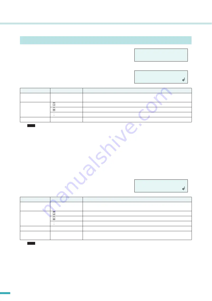
Here’s how to recall or store scenes for a specified amplifier.

Recalling a scene (“1. Scene” 

 “Recall”)

Recalls a scene for the specified amplifier.

• If you select “ALL” as the Amp ID, the scene name will not be displayed.

• If you select “ALL” as the Amp ID, amplifiers for which there is no correspondingly-numbered scene data will not recall a 

scene; they will retain their previous state.

• Scene number 00 is for returning the amplifiers to their default settings.

• If characters not supported by the ACD1 were used for the scene name in Amp Editor, the corresponding locations will 

be shown as “

~

.” For details on the characters supported by the ACD1, refer to 

“List of supported characters” (page 21)

 at 

the end of this manual.

• Scene names that can be displayed by the ACD1 are a maximum of 12 characters. If a scene name of 13 characters or 

longer is specified in Amp Editor, the ACD1 will not display the thirteenth and subsequent character.

• If you edit a parameter after recalling a scene, the E symbol (edit symbol) will be shown in screens that show the scene 

number.

Storing a scene (“1. Scene” 

 “Store”)

Stores a scene for the specified amplifier.

• If the screen indicates “(scene number):(scene name) Overwrite?”, scene data has already been stored in the selected 

scene. If you want to overwrite the existing data, press the [

INC/YES] button. If you want to store the settings to a dif-

ferent scene number without overwriting, press the [

DEC/NO] button, then press the [BACK] button several times, 

and re-select the scene number for storing.

• Scene data is saved in the ACD1, not in each amplifier.

• Stored scene data is valid only for the identical model of amplifier. Scene data will be ignored if a different model of ampli-

fier is connected with the same Amp ID.

• When you store a scene, the E symbol shown in screens that indicate the scene number will disappear.

Scene (“1. Scene”)

Parameter

Range

Explanation

Amp ID

00–39, ALL

Selects the ID of the amplifier for which to recall a scene. If you select “ALL,” the cor-
respondingly-numbered scene will be recalled for all amplifiers.

Attributes of the 
scene

Preset scene

A user scene that is protected

A user scene that is not protected

Scene No.

00–49

Selects the scene number to be recalled.

Parameter

Range

Explanation

Amp ID

00–39, ALL

Selects the ID of the amplifier for which to store a scene. If you select “ALL,” the cur-
rent scene will be stored to the selected scene number of all amplifiers.

Attributes of the 
scene

Preset scene

A user scene that is protected

A user scene that is not protected

Scene No.

01–49

Selects the scene number to be stored.

Scene name

See character list at 
the end of this manual

Enter the name of the scene to store. A maximum of 12 characters can be entered.

å

1.Scene

Recall

å

Amp ID:

01

01:Scene Name

NOTE

å

Amp ID:

01

01:Scene Name

NOTE

Содержание ACD1

Страница 1: ...EN Reference Manual ...

Страница 2: ... Utility Firmware Ver 13 LCD backlight 5 Utility LCD Backlight 14 Restricting panel operations 5 Utility Panel Operation 14 Enabling scene recall operations from the panel 5 Utility Scene Recall 14 Enabling scene recall operations via EMG commands 5 Utility EMG Scene Setup 15 LAST MEMORY RESUME setting 5 Utility Last Mem Resume 15 Clock setting 5 Utility Clock 15 GPI IN calibration 5 Utility GPI C...

Страница 3: ...pported amplifiers As of September 2009 the following amplifiers support connection with the ACD1 XP series XP7000 XP5000 XP3500 XP2500 XP1000 XM series XM4180 XM4080 XH series XH200 PC N series PC9501N PC6501N PC4801N PC3301N PC2001N PC9500N PC4800N PC3300N Tn series T5n T4n T3n For the most recent information refer to the following URL http www yamahaproaudio com Setup For details on setting up ...

Страница 4: ... recalling scenes for multiple amplifiers within an area are called a scene link By recalling a scene link scenes can be simultaneously recalled for multiple amplifiers Scene links can be created and recalled using Amp Editor Device ID This is an ID for uniquely identifying an ACD1 unit within a network If there are duplicate IDs within an area it will be impossible to monitor control them from Am...

Страница 5: ...o the ACD1 is turned off To reset the FAULT OUTPUT connector output to connect NC and C press and hold down the BACK and DEC NO buttons simultaneously for a few seconds while the HOME screen is displayed to display the message Reset FaultOut Are you sure Then press the INC YES button This operation is effective only when the FAULT OUTPUT connector indicates an abnormality r NEXT button Use this to...

Страница 6: ...put and 4 port output The V terminals have an output voltage of 5 volts The IN terminals detect voltage changes from 0V to 5V The OUT terminals are open collector outputs and change between Open and Close For details on connections and usage refer to Connector wiring page 18 For details on calibrating the GPI IN connectors refer to Utility page 13 0 FAULT OUTPUT connectors This is a Euroblock conn...

Страница 7: ...firmware version LCD Backlight Selects whether the ACD1 s LCD backlight will be always lit ON or lit only during operation Auto OFF Panel Operation Restricts panel operations of the ACD1 Scene Recall Specifies whether scene recall from the ACD1 s panel is enabled Enable or dis abled Disable EMG Scene Setup Specifies the scene number that will be recalled when the EMG Emergency sig nal is received ...

Страница 8: ...reen or parameter BACK Moves to the previous screen or parameter INC YES Increments the value of a parameter INC or responds YES in response to a confirmation message DEC NO Decrements the value of a parameter DEC or responds NO in response to a confirmation message Press the INC YES but ton Press Increments the value of a parameter Press and hold Continues to increment the value of a parameter wh...

Страница 9: ...cute the Store operation Do not turn off the power while the Do not turn off indication is shown If you press the DEC NO button you will return to step 13 without storing If the display indicates Parameter Locked Panel Operation is set to View Only To temporarily defeat the panel lock hold down both the INC YES DEC NO buttons for at least three seconds To disable the panel lock first defeat it tem...

Страница 10: ... the existing data press the INC YES button If you want to store the settings to a dif ferent scene number without overwriting press the DEC NO button then press the BACK button several times and re select the scene number for storing Scene data is saved in the ACD1 not in each amplifier Stored scene data is valid only for the identical model of amplifier Scene data will be ignored if a different ...

Страница 11: ...hed If you select ALL the power of all amplifiers will be switched to the specified state Power supply status Standby On Selects the status of the power supply Parameter Range Explanation Amp ID 00 39 ALL Selects the ID of the amp whose channel is to be muted If you select ALL the mute status for all channels of all amplifiers will be switched Amp Ch A H ALL Selects the channel whose mute status i...

Страница 12: ... will appear View ACD1 name 4 Device Setup Device Label Displays the name of the ACD1 assigned by Amp Editor This shows up to 14 alphanumeric characters The fifteenth and following characters will not be shown Characters not appearing in the character list at the end of this manual are displayed as Amplifier output monitor 3 Output Monitor Parameter Range Explanation Amp ID 00 39 Selects the ID of...

Страница 13: ... ACD1 owner s manual to have the backup battery replaced Version indication 5 Utility Firmware Ver Displays the ACD1 s firmware version You can use Amp Editor to update the ACD1 s firmware For details refer to the Amp Editor owner s manual You can download the latest firmware from the download page of the following Yamaha website http www yamahaproaudio com Parameter Range Explanation Identify ON ...

Страница 14: ...area may indicate Some ON This means that scene recall is enabled for some amplifiers but disabled for other amplifiers Parameter Range Explanation LCD Backlight ON The backlight will stay lit Auto OFF The backlight will go dark automatically It will light when you perform a panel operation and will automatically go dark ten sec onds afterward Parameter Range Explanation Panel Operation Normal Pan...

Страница 15: ... and time of the ACD1 s internal clock The seconds will be set to 00 when you finalize the time If Daylight Saving Time is enabled in Amp Editor this will indicate DST Parameter Range Explanation Amp ID 00 39 ALL Specifies the ID of the amp for which EMG scene recall will be enabled If you select ALL the EMG scene recall enable status of all amplifiers will be switched to the specified state EMG S...

Страница 16: ...the ACD1 s NETWORK connector Parameter Range Explanation Port No 1 4 Selects the port of the GPI IN connector that will be calibrated Minimum maximum value setting Min Max Selects whether you will be setting the minimum Min or maximum Max value for the input voltage Voltage value Indicates the input voltage At the left of the symbol is shown the specified voltage maximum minimum value and at the r...

Страница 17: ...en performing the following steps 1 Power off the ACD1 2 While holding down the BACK button turn the power on 3 Press the INC YES button to initialize the internal memory Do not turn off the power during the initialization process 4 When initialization is completed the ACD1 will automatically restart The log data is preserved even if you execute initialization Parameter Range Port number hexadecim...

Страница 18: ...ctor strip the wire as shown in the illustration and use stranded wire to make connections With a Euroblock connection the stranded wire may be prone to breakage because of metal fatigue due to the weight of the cable or due to vibration When rack mount ing your equipment use a lacing bar when possible to bundle and fasten the cables If cables will be frequently connected and disconnected as in th...

Страница 19: ...ock plug connection page 18 in this manual By specifying the input output channels in Amp Editor you can recall scenes or edit parameters from a connected exter nal GPI device or send signals to an external GPI device For details on making settings refer to the Amp Editor owner s manual To adjust calibrate the range over which the input voltage to the GPI connector is detected refer to 5 Utility p...

Страница 20: ...k plugs are used for the FAULT OUTPUT connector Euroblock connection methods are described in Euroblock plug connection page 18 in this manual In Amp Editor s Device Setup menu Alert Setup you can set Type to Fault so that a fault can be indicated by a con nected lamp etc For details on making settings refer to the Amp Editor owner s manual The relay contacts are rated for a resistive load of 1A D...

Страница 21: ...t turn off A file is being written to internal memory Never turn off the power while this message is shown Initializing Do not turn off Internal memory is being initialized Never turn off the power while this message is shown Updating f ware Do not turn off The firmware is being updated Never turn off the power while this message is shown Synchronizing Do not turn off Now synchronizing with Amp Ed...

Страница 22: ... with Amp Editor A cable is disconnected or broken Check whether a cable might be disconnected or broken Amplifier does not oper ate as specified The amplifier was powered on before the ACD1 Power on the equipment so that the ACD1 starts up before the amplifiers connected to the ACD1 Can t monitor control an amplifier A cable is disconnected or broken Check whether a cable might be disconnected or...

Страница 23: ...ol I O Terminal Format Level Connector MONITOR REMOTE 1 D SUB 15P Female 8 DATA PORT 2 RS 485 RS 485 RJ 45 GPI 3 IN 0 5 V Euroblock 3 5 mm pitch OUT Open Collector V 5 V FAULT OUTPUT 4 NETWORK IEEE 802 3 10Base T 100Base TX RJ 45 Pin Assignment 1 GND 2 REMOTE CONTROL STANDBY 3 MONITOR MODEL ID 4 REMOTE CONTROL MUTE CH D 5 MUTE CH C 6 MUTE CH B 7 MUTE CH A 8 MONITOR PROTECT STATUS CH D 9 PROTECT ST...

Страница 24: ...al are for information purposes only Yamaha Corp reserves the right to change or modify products or specifications at any time without prior notice Since spec ifications equipment or options may not be the same in every locale please check with your Yamaha dealer Dimensions 480 1 44 3 354 362 5 ...

Страница 25: ...U R G Pro Audio Division 2009 Yamaha Corporation 004 PO D0 ...

Отзывы: