


THROTTLE BODY
7-9
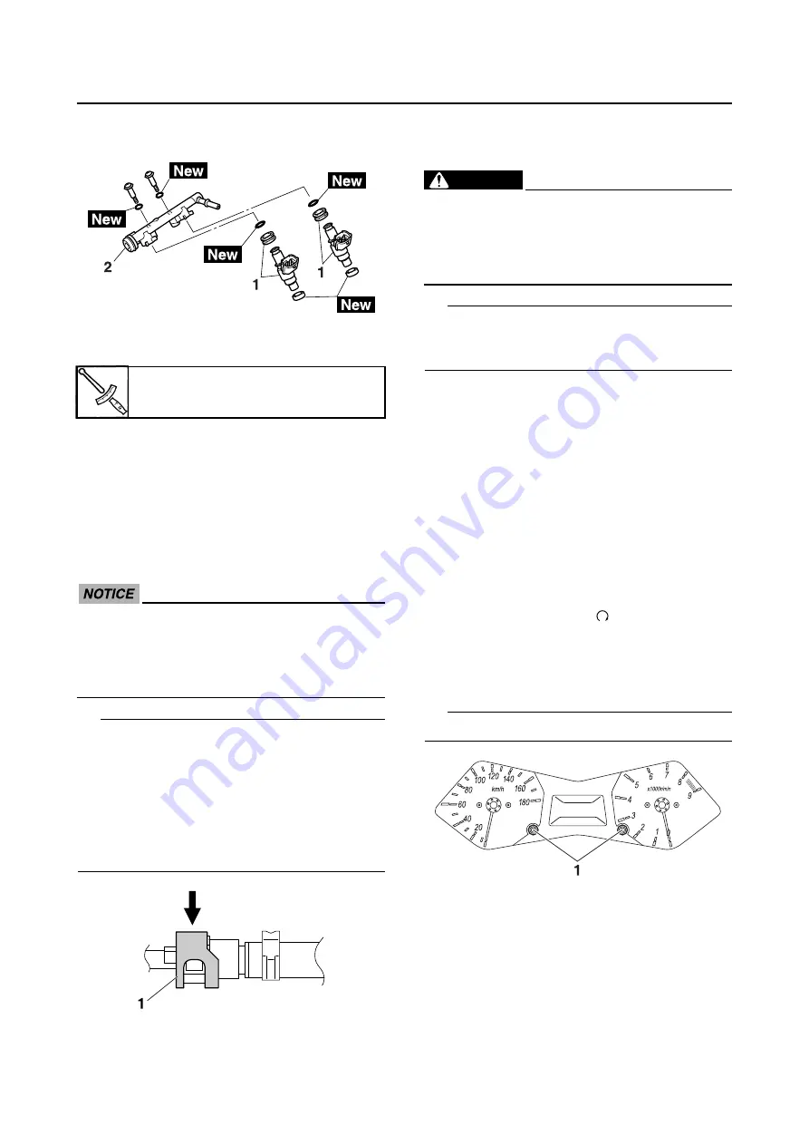
3. Install a new seal onto the end of each
injector.
4. Install the injector assembly to the intake
manifold with the screws and new gaskets.
5. Check the fuel pressure.
Refer to “CHECKING THE FUEL PRES-
SURE” on page 7-3.
EAS59C1707
INSTALLING THE FUEL HOSE (INJECTOR
SIDE)
1. Connect:
• Fuel hose (injector side)
ECA59C1706
When installing the fuel hose, make sure
that it is securely connected, and that the
fuel hose connector cover on the fuel hose
is in the correct position, otherwise the fuel
hose will not be properly installed.
TIP
• Install the fuel hose securely onto the fuel rail
until a distinct “click” is heard.
• To install the fuel hose onto the fuel rail, slide
the fuel hose connector cover “1” on the end
of the hose in the direction of the arrow
shown.
• It is prohibited to wear the cotton work gloves
or equivalent coverings.
EAS59C1706
ADJUSTING THE THROTTLE POSITION
SENSOR
WARNING
EWA59C1701
• Handle the throttle position sensor with
special care.
• Never subject the throttle position sensor
to strong shocks. If the throttle position
sensor is dropped, replace it.
TIP
Before adjusting the throttle position sensor,
the engine idling speed should be properly
adjusted.
1. Check:
• Throttle position sensor
Refer to “CHECKING THE THROTTLE
POSITION SENSOR” on page 8-139.
2. Adjust:
• Throttle position sensor angle
▼▼▼▼▼▼▼▼▼▼▼▼▼▼▼▼▼▼▼▼▼▼▼▼▼▼▼▼▼▼
a. Temporary tighten the throttle position sen-
sor.
b. Check that the throttle grip is fully closed.
c. Connect the throttle position sensor to the
wire harness.
d. Set the main switch to “OFF” and set the
engine stop switch to “
”.
e. Simultaneously press and hold the left set
and right set buttons “1”, set the main
switch to “ON”, and continue to press the
buttons for 8 seconds more.
TIP
“dIAG” appears on the odometer LCD.
f.
Diagnostic code number “d:01” is selected.
g. Adjust the position of the throttle position
sensor angle so that 14–20 can appear in
the meter.
h. After adjusting the throttle position sensor
angle, tighten the throttle position sensor
screws “2”.
Fuel rail screw
3.5 Nm (0.35 m·kgf, 2.5 ft·lbf)
Содержание 2012 TMAX XP500A
Страница 1: ...SERVICE MANUAL XP500A 2012 59C 28197 E1 ...
Страница 6: ......
Страница 8: ......
Страница 54: ...SPECIAL TOOLS 1 45 ...
Страница 79: ...LUBRICATION POINTS AND LUBRICANT TYPES 2 24 ...
Страница 82: ...LUBRICATION SYSTEM CHART AND DIAGRAMS 2 27 EAS20410 LUBRICATION DIAGRAMS ...
Страница 84: ...LUBRICATION SYSTEM CHART AND DIAGRAMS 2 29 ...
Страница 86: ...LUBRICATION SYSTEM CHART AND DIAGRAMS 2 31 ...
Страница 87: ...LUBRICATION SYSTEM CHART AND DIAGRAMS 2 32 1 Oil strainer 2 Intake camshaft 3 Exhaust camshaft ...
Страница 88: ...LUBRICATION SYSTEM CHART AND DIAGRAMS 2 33 ...
Страница 90: ...COOLING SYSTEM DIAGRAMS 2 35 EAS20420 COOLING SYSTEM DIAGRAMS ...
Страница 92: ...COOLING SYSTEM DIAGRAMS 2 37 ...
Страница 94: ...CABLE ROUTING 2 39 EAS20430 CABLE ROUTING Handlebar top side view ...
Страница 96: ...CABLE ROUTING 2 41 Handlebar front side and left side view ...
Страница 98: ...CABLE ROUTING 2 43 Front brake front side and left side view ...
Страница 100: ...CABLE ROUTING 2 45 Frame front side view ...
Страница 102: ...CABLE ROUTING 2 47 Frame left side view ...
Страница 104: ...CABLE ROUTING 2 49 Frame right side view ...
Страница 106: ...CABLE ROUTING 2 51 Rear frame top side and right side view ...
Страница 108: ...CABLE ROUTING 2 53 Rear brake top side and left side view ...
Страница 110: ...CABLE ROUTING 2 55 Throttle body left side view ...
Страница 112: ...CABLE ROUTING 2 57 Fuel tank top side left side and right side view ...
Страница 114: ...CABLE ROUTING 2 59 Hydraulic unit top side and front side view ...
Страница 116: ...CABLE ROUTING 2 61 ...
Страница 119: ......
Страница 154: ...PERIODIC MAINTENANCE 3 35 ...
Страница 183: ...FRONT WHEEL 4 26 8 Check Front wheel sensor installation Check if the wheel sensor housing is installed properly ...
Страница 245: ...FRONT FORK 4 88 3 Install Cap bolt cover right front fork side Upper bracket pinch bolt 30 Nm 3 0 m kgf 22 ft lbf 1 ...
Страница 258: ...SWINGARM 4 101 ...
Страница 263: ...ENGINE INSPECTION 5 2 9 Connect Spark plug caps 10 Install Radiator cover Refer to GENERAL CHASSIS on page 4 1 ...
Страница 329: ...OIL PUMP 5 68 ECA13890 After tightening the bolts make sure the oil pump turns smoothly ...
Страница 346: ...TRANSMISSION 5 85 ...
Страница 351: ...RADIATOR 6 4 b Apply 137 3 kPa 1 37 kgf cm2 19 9 psi of pressure c Measure the indicated pressure with the gauge ...
Страница 371: ...THROTTLE BODY 7 10 Throttle position sensor screw 3 5 Nm 0 35 m kgf 2 5 ft lbf ...
Страница 372: ...THROTTLE BODY 7 11 ...
Страница 375: ......
Страница 376: ...IGNITION SYSTEM 8 1 EAS27090 IGNITION SYSTEM EAS27110 CIRCUIT DIAGRAM ...
Страница 380: ...ELECTRIC STARTING SYSTEM 8 5 EAS27160 ELECTRIC STARTING SYSTEM EAS27170 CIRCUIT DIAGRAM ...
Страница 386: ...CHARGING SYSTEM 8 11 EAS27200 CHARGING SYSTEM EAS27210 CIRCUIT DIAGRAM ...
Страница 387: ...CHARGING SYSTEM 8 12 2 AC magneto 3 Rectifier regulator 4 Frame ground 5 Joint 19 Battery 20 Negative lead 21 Main fuse ...
Страница 389: ...CHARGING SYSTEM 8 14 ...
Страница 390: ...LIGHTING SYSTEM 8 15 EAS27240 LIGHTING SYSTEM EAS27250 CIRCUIT DIAGRAM ...
Страница 394: ...SIGNALING SYSTEM 8 19 EAS27270 SIGNALING SYSTEM EAS27280 CIRCUIT DIAGRAM ...
Страница 399: ...SIGNALING SYSTEM 8 24 ...
Страница 400: ...COOLING SYSTEM 8 25 EAS27300 COOLING SYSTEM EAS27310 CIRCUIT DIAGRAM ...
Страница 404: ...FUEL INJECTION SYSTEM 8 29 EAS27331 FUEL INJECTION SYSTEM EAS27340 CIRCUIT DIAGRAM ...
Страница 445: ...FUEL INJECTION SYSTEM 8 70 ...
Страница 446: ...FUEL PUMP SYSTEM 8 71 EAS27550 FUEL PUMP SYSTEM EAS27560 CIRCUIT DIAGRAM ...
Страница 449: ...FUEL PUMP SYSTEM 8 74 ...
Страница 450: ...IMMOBILIZER SYSTEM 8 75 EAS27640 IMMOBILIZER SYSTEM EAS27650 CIRCUIT DIAGRAM ...
Страница 459: ...IMMOBILIZER SYSTEM 8 84 ...
Страница 460: ...ABS ANTI LOCK BRAKE SYSTEM 8 85 EAS28790 ABS ANTI LOCK BRAKE SYSTEM EAS27730 CIRCUIT DIAGRAM ...
Страница 462: ...ABS ANTI LOCK BRAKE SYSTEM 8 87 EAS27740 ABS COMPONENTS CHART ...
Страница 464: ...ABS ANTI LOCK BRAKE SYSTEM 8 89 EAS27750 ABS COUPLER LOCATION CHART ...
Страница 468: ...ABS ANTI LOCK BRAKE SYSTEM 8 93 EAS27810 BASIC PROCESS FOR TROUBLESHOOTING ...
Страница 493: ...ABS ANTI LOCK BRAKE SYSTEM 8 118 ...
Страница 494: ...ELECTRICAL COMPONENTS 8 119 EAS27973 ELECTRICAL COMPONENTS ...
Страница 496: ...ELECTRICAL COMPONENTS 8 121 ...
Страница 498: ...ELECTRICAL COMPONENTS 8 123 EAS27981 CHECKING THE SWITCHES ...
Страница 527: ......
Страница 528: ......


