background image

VALVES AND VALVE SPRINGS 

EAS00240 

CHECKING THE VALVE SEATS 
The following procedure applies to all of the 

valves and valve seats. 

1. Eliminate: 

 carbon deposits 

(from the valve face and valve seat) 

2. Check: 

 valve seat 

Pitting/wear

 -*

 Replace the cylinder head. 

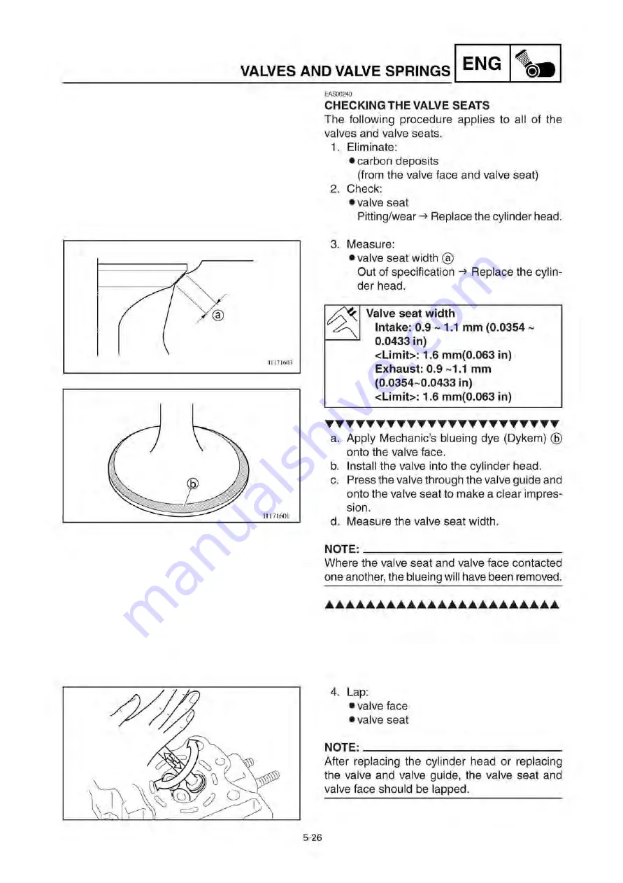
3. Measure: 

 valve seat width a 

Out of specification

 -*

 Replace the cylin-

der head. 

Valve seat width 

Intake: 0.9 ~ 1.1 mm (0.0354 ~ 
0.0433 in) 
<Limit>: 1.6 mm(0.063 in) 
Exhaust: 0.9 ~1.1 mm 
(0.0354~0.0433 in) 
<Limit>: 1.6 mm(0.063 in) 

T T T T T T T T T T T T T T T T T T T T T T T 

a. 

b. 
c. 

d. 

Apply Mechanic’s blueing dye (Dykem) b 
onto the valve face. 
Install the valve into the cylinder head. 
Press the valve through the valve guide and 
onto the valve seat to make a clear impres-
sion. 
Measure the valve seat width. 

NOTE: 
Where the valve seat and valve face contacted 
one another, the blueing will have been removed. 

• • • • • • • • • • • • • • • • • • • • • • • 

4. Lap: 

8valve face 
8valve seat 

NOTE: 
After replacing the cylinder head or replacing 
the valve and valve guide, the valve seat and 
valve face should be lapped. 

5-26 

Downloaded 

from 

www.ScooterTime.net

Содержание 2006 XF50W

Страница 1: ... YAMAHA XF50W SERVICE MANUAL LIT 11616 20 58 3B3 F8197 10 D o w n l o a d e d f r o m w w w S c o o t e r T i m e n e t ...

Страница 2: ...td First edition September 2006 All rights reserved Any reproduction or unauthorized use without the written permission of Yamaha Motor Taiwan Co Ltd is expressly prohibited Printed in U S A LIT 11616 20 58 D o w n l o a d e d f r o m w w w S c o o t e r T i m e n e t ...

Страница 3: ...ns and significant changes in specifications or procedures will be forwarded to all authorized Yamaha dealers and will appear in future editions of this manual where applicable NOTE Designs and specifications are subject to change without notice EAS00005 IMPORTANT MANUAL INFORMATION Particularly important information is distinguished in this manual by the following Q w cC NOTE The Safety Alert Sym...

Страница 4: ...requiring more information such as special tools and technical data are described se quentially 6 2 4 5 7 Order Job Part Q ty Remarks 1 2 3 4 5 6 7 8 Removing the cylinder and piston Cylinder head Timing chain guide exhaust side Cylinder Dowel pin Cylinder gasket Piston pin clip Piston pin Piston Piston ring set 1 1 2 1 2 1 1 1 Remove the parts in the order listed Refer to CYLINDER HEAD Refer to R...

Страница 5: ... 9 Troubleshooting Symbols 0 to u indicate the following 0 Serviceable with engine mounted q Filling fluid w Lubricant e Special tool r Tightening torque t Wear limit clearance y Engine speed u Electrical data Symbols i to d in the exploded diagrams indi cate the types of lubricants and lubrication points i Engine oil o Gear oil p Molybdenum disulfide oil a Wheel bearing grease s Lithium soap base...

Страница 6: ...PECIFICATIONS 0 SPEC 2 PERIODIC CHECKS AND ADJUSTMENTS CHK ADJ 3 CHASSIS CHASSIS CHAS 4 ENGINE ENG 5 COOLING SYSTEM COOL 6 FUEL INJECTION SYSTEM FI 5 ELECTRICAL SYSTEM ELEC 8 TROUBLESHOOTING B L SHTG D o w n l o a d e d f r o m w w w S c o o t e r T i m e n e t ...

Страница 7: ... 1 2 FI SYSTEM 1 3 IMPORTANT INFORMATION 1 4 PREPARATION FOR REMOVAL AND DISASSEMBLY 1 4 REPLACEMENT PARTS 1 4 GASKETS OIL SEALS AND O RINGS 1 4 LOCK WASHERS PLATES AND COTTER PINS 1 5 BEARINGS AND OIL SEALS 1 5 CIRCLIPS 1 5 EQUIPMENT PREPARATION 1 6 CHECKING THE CONNECTIONS 1 7 SPECIAL TOOLS 1 8 D o w n l o a d e d f r o m w w w S c o o t e r T i m e n e t ...

Страница 8: ...AS00017 VEHICLE IDENTIFICATION NUMBER The vehicle identification number 1 is stamped into the frame EAS00018 MODEL LABEL The model label 1 is affixed to the frame trunk This information will be needed to order spare parts 1 1 D o w n l o a d e d f r o m w w w S c o o t e r T i m e n e t ...

Страница 9: ...gine to deliver more performance and cleaner exhaust gases in crease it becomes necessary to control the air fuel ratio in a more precise and finely tuned manner To accommodate this need this model has adopted an electronically controlled fuel injection FI system in place of the conventional carburetor system This system can achieve an optimum air fuel ratio required by the engine at all times by ...

Страница 10: ...pplied The injection duration and the injection timing are controlled by the ECU Signals that are input from the crankshaft position sensor intake air pressure sensor intake temperature sensor and engine temperature sensor enable the ECU to determine the injection duration The injection timing is deter mined through the signals from the crankshaft position sensor As a result the volume of fuel tha...

Страница 11: ...s in the order of dis assembly This will speed up assembly and allow for the correct installation of all parts 5 Keep all parts away from any source of fire 1 N M EAS00021 REPLACEMENT PARTS Use only genuine Yamaha parts for all replace ments Use oil and grease recommended by Yamaha for all lubrication jobs Other brands may be similar in function and appearance but infe rior in quality EAS00022 GAS...

Страница 12: ...ricate the oil seal lips with a light coat of lithium soap based grease Oil bearings liberally when installing if appropriate 1 Oil seal cC Do not spin the bearing with compressed air because this will damage the bearing surfaces 1 Bearing EAS00025 CIRCLIPS Before reassembly check all circlips carefully and replace damaged or distorted circlips Al ways replace piston pin clips after one use When i...

Страница 13: ...type Dissembling 1 Press center pin1 inward to release the lock 2 Remove the push rivet main body2 Assembling 1 Restore the center pin replace the push rivet main body 2 Push in the center pin until leveling off with the surface position of the push rivet main body 1 6 D o w n l o a d e d f r o m w w w S c o o t e r T i m e n e t ...

Страница 14: ...ction Connect properly NOTE If the pin on the terminal is flattened bend it up k k k k V ff Y v V 1 A 1 A 1 4 Connect 8lead 8coupler 8connector NOTE Make sure all connections are tight 5 Check 8continuity with the pocket tester p Pocket tester 90890 03112 YU 03112 C NOTE 8 If there is no continuity clean the terminals 8 When checking the wire harness perform steps 1 to 3 8 As a quick remedy use a ...

Страница 15: ... YM 33285 6 90890 01325 YU 24460 01 90890 01352 YU 33984 90890 01367 YM A9409 7 90890 01400 YM A9409 3 Meter gear bush tool This tool is used when removing or install ing the meter gear Slide hammer bolt 8mm 1 Weight2 These tools are needed to remove the cam shaft 2 Rotor holding tool This tool is used to hold the primary fixed sheave and secondary sheave assembly Ring nut wrench This tool is used...

Страница 16: ...nut wrench 45mm This tool is used to loosen and tighten the upper bearing inner race Flywheel puller set This tool is used to remove the AC magneto rotor Socket wrench 39mm This tool is used when removing or install ing the secondary sheave nut Sheave holder This tool is used for holding the secondary sheave Thickness gauge This tool is used to measure the valve cleanance Compression gauge This to...

Страница 17: ...ers Middle driven shaft bearing driver1 Mechanical seal installer2 There tools are used to install the water pump seal Valve spring compressor Compressor adapter Ø16 5mm These tools are used when removing or in stalling the valve and the valve spring Digital tachometer This tool is needed for detecting engine rpm Ignition checker This tool is used to check the ignition sys tem components Valve gui...

Страница 18: ...se tools are used to hold the damper rod when removing or installing the damper rod D Pressure gauge This tool is used to measure fuel pressure Fuel pressure adapter This tool is used to measure fuel pressure Yamaha bond NO 1215 Sealant Quick Gasket This sealamt bond is used on crankcase mating surfaces e g crankcase mating sur faces 1 11 D o w n l o a d e d f r o m w w w S c o o t e r T i m e n e...

Страница 19: ...TRICAL SPECIFICATIONS 2 15 CONVERTION TABLE GENERAL TIGHTENING TORQUE SPECIFICA TIONS 2 18 TIGHTENING TORQUES 2 19 ENGINE 2 19 CHASSIS 2 21 LUBRICATION POINTS AND LUBRICANT TYPES 2 23 ENGINE 2 23 CHASSIS 2 25 COOLING SYSTEM DIAGRAMS 2 26 CABLE ROUTING 2 29 D o w n l o a d e d f r o m w w w S c o o t e r T i m e n e t ...

Страница 20: ...heelbase Minimum ground clearance Minimum turning radius 1905mm 75 00in 685mm 26 97in 1045mm 41 14in 735mm 28 94in 1280mm 50 39in 115mm 4 53in 2000mm 78 74in Weight Wet without oil and a full fuel tank Dry without oil and fuel Maximun load total of cargo rider passenger and accessories 90kg 198lb 85kg 187lb 175kg 386lb 2 1 D o w n l o a d e d f r o m w w w S c o o t e r T i m e n e t ...

Страница 21: ...el Unleaded gasoline only USA Regular unleaded gasoline only CAN Fuel tank capacity Total 4 5L 0 98 Imp gal 1 18 US gal Engine oil Lubrication system Wet sump Recommended oil YAMALUBE4 SAE10W30 or SAE20W40 API service SG type or higher JASO stand MA Quantity Periodic oil change 0 73 0 83L 0 67 0 76 Imp qt 0 80 0 90 US qt Total amount 0 80 0 90L 0 74 0 83 Imp qt 0 87 0 98 US qt Final gear oil Recom...

Страница 22: ...pressure 1 1kPa 0 01kg cm2 0 16psi Radiator core Width 127 4mm 5 016in Height 87mm 3 425in Depth 16mm 0 630in Coolant reservoir Capacity up to the maximum level mark 0 25L 0 22 Imp gal 0 27 US gal From low to full level 0 15L 0 13 Imp gal 0 16 US gal Water pump Water pump type Single suction centrifugal pump Max impeller shaft tilt 0 15mm 0 0059in Starting system type Electric and kick starter Ele...

Страница 23: ...sions 6A B Measurement A Measurement B Maximum camshaft runout Chain drive left 30 158 30 258mm 1 1873 1 1913in 25 082 25 182mm 0 9875 0 9914in 30 158 30 258mm 1 1873 1 1913in 25 020 25 120mm 0 9850 0 9890in 30 058mm 1 1834in 24 982mm 0 9835in 30 058mm 1 1834in 24 920mm 0 9811in 0 03mm 0 0012in 2 4 D o w n l o a d e d f r o m w w w S c o o t e r T i m e n e t ...

Страница 24: ...6457 0 6535in Valve face width B Intake 1 48 2 19mm 0 0583 0 0862in Exhaust 1 48 2 19mm 0 0583 0 0862in Valve seat width C Intake 0 9 1 1mm 1 6mm 0 0354 0 0433in 0 0630in Exhaust 0 9 1 1mm 1 6mm 0 0354 0 0433in 0 0630in Valve margin thickness D Intake 0 70mm 0 0276in Exhaust 0 70mm 0 0276in Valve stem diameter Intake 3 975 3 990mm 3 945mm 0 1565 0 1571in 0 1553in Exhaust 3 975 3 990mm 3 930mm 0 15...

Страница 25: ...e stem runout w Valve seat width Intake Exhaust 0 010 0 037mm 0 0004 0 0015in 0 025 0 052mm 0 0010 0 0020in 0 9 1 1mm 0 0354 0 0433in 0 9 1 1mm 0 0354 0 0433in 0 080mm 0 0031in 0 100mm 0 0039in 0 010mm 0 0004in 1 6mm 0 0630in 1 6mm 0 0630in 2 6 D o w n l o a d e d f r o m w w w S c o o t e r T i m e n e t ...

Страница 26: ...3 58lb Exhaust 107 9 124 1N 11 0 12 7kg 24 26 27 90lb Spring tilt V A Intake 2 5 1 7mm 2 5 0 0669in Exhaust 2 5 1 8mm 2 5 0 0709in Winding direction top view Intake Clockwise Exhaust Clockwise Valve seat reformed Yes Cylinder Cylinder arrangement Forward inclined single cylinder Bore stroke 38 0 43 5mm 1 496 1 713in Compression ratio 12 1 Bore 38 000 38 010mm 1 496 1 497in Maximum taper 0 05mm 0 0...

Страница 27: ...g side clearance 0 010 0 035mm 0 0004 0 0014in 37 975 37 990mm 1 4951 1 4957in 5 0mm 0 1969in 10 002 10 013mm 0 3938 0 3942in 0 35 0 65mm 0 0138 0 0256in Intake side 9 996 10 000mm 0 3935 0 3937in Taper 0 8 1 5mm 0 0315 0 0591in 0 05 0 17mm 0 0020 0 0067in 0 02 0 06mm 0 0008 0 0024in 0 150mm 0 0059in 10 043mm 0 3954in 9 976mm 0 3928in Barrel 0 8 1 65mm 0 0315 0 0650in 0 05 0 15mm 0 40mm 0 0020 0 0...

Страница 28: ...Standard Limit Oil ring i 1 B 1 i i T Dimensions B T 1 5 1 6mm 0 0591 0 0630in End gap installed 0 2 0 7mm 0 0079 0 0276in Ring side clearance 0 03 0 15mm 0 0012 0 0059in 2 9 D o w n l o a d e d f r o m w w w S c o o t e r T i m e n e t ...

Страница 29: ...0 0004 0 0013in 10 030mm 0 3949in 9 950mm 0 3917in Connecting rod Connecting rod length Small end inside diameter 79 95 80 05mm 3 1476 3 1516in 10 015 10 028mm 0 3943 0 3948in Crankshaft Width A Maximum runout C Big end side clearance D Big end radial clearance E 1 42 45 42 50mm 1 671 1 673in 0 15 0 45mm 0 006 0 018in 0 0 010mm 0 0 0004in 0 03mm 0 0012in 1 00mm 0 0394in 2 10 D o w n l o a d e d f ...

Страница 30: ... 0 705in 16 1mm 0 634in Transmission Transmission type Primary reduction system Primary reduction ratio Secondary reduction system Secondary reduction ratio Single speed automatic Maximum main axle runout Maximum drive axle runout V belt automatic Helical gear 50 13 3 846 Helical gear 43 12 3 583 3 087 0 945 1 0 04mm 0 002in 0 04mm 0 002in Air filter type Wet element Fuel pump Pump type Model manu...

Страница 31: ...MT3 00 Aluminum 58mm 2 28in 1 0mm 0 04in 1 0mm 0 04in 0 25mm 0 01in Rear wheel Wheel type Rim Size Material Wheel travel Wheel runout Maximum radial wheel runout Maximum lateral wheel runout Cast wheel J10 MT3 00 Aluminum 56mm 2 20in 1 0mm 0 04in 1 0mm 0 04in Front tire Tire type Size Model manufacturer Tire pressure cold 0 175kg 0 386lb Minimum tire tread depth Tubeless 120 90 10 57J C 6022 CHENG...

Страница 32: ...ay at lever end Brake drum inside diameter Lining thickness Drum brake Left hand operation 10 20mm 0 39 0 79in 110mm 4 33in 4 0mm 0 16in 110 5mm 4 35in 2 0mm 0 08in Front suspension Suspension type Front fork type Front fork travel Spring Free length Installed length Spring rate K1 Spring stroke K1 Optional spring available Fork oil Recommended oil Quantity each front fork leg Inner tube outer dia...

Страница 33: ...ck absorber assembly type Coil spring Rear shock absorber assembly travel 45mm 1 77in Spring Free length 176 5mm 6 95in Installed length 162 5mm 6 40in Spring rate K1 28 03N mm 2 85kg mm 159 59lb in Spring rate K2 42 18N mm 4 30kg mm 240 79lb in Spring stroke K1 0 17mm 0 0 67in Spring stroke K2 17 45mm 0 67 1 77in Optional spring available No 2 14 D o w n l o a d e d f r o m w w w S c o o t e r T ...

Страница 34: ...system System type AC magneto Model manufacturer F3B3 T MORIC Nominal output 14V 130W 5000r min Stator coil resistance color 0 28 0 42 at 20 C 68 F white white Rectifier regulator Regulator type Semiconductor short circuit Model manufacturer SH745 AA SHINDENGEN No load regulated voltage 13 0 14 0V Rectifier capacity 24A Withstand voltage 200V Battery Battery type manufacturer GTX5L BS GS Battery v...

Страница 35: ... Constant mesh 3B3 00 T MORIC 12V 0 25kW 7 0mm 0 28in 2 3 92 5 88N 400 600gf 14 11 21 16oz 17 6mm 0 69in 0 0378 0 0462 at 20 C 68 F 1 35mm 0 05in 3 5mm 0 14in 16 6mm 0 65in Starter relay Model manufacturer Amperage Coil resistance Suction voltage 5WC 00 OMRON 50A 90 110 More than DC10V Horn Horn type Model manufacturer Maximum amperage Performance Coil resistance Plane GF 127 NIKKO 1 0A 95 115dB 2...

Страница 36: ...re sensor Model manufacturer Coil resistance at 20 C 68 F Coil resistance at 80 C 176 F 5YP1 DENSO 2 32 2 59k 2 0 310 0 326k 2 Intake air pressure sensor Output voltage 0 789 4 0V Intake air temperature sensor Coil resistance color 5 7 6 3k at 20 C 68 F brown white black blue Speed sensor Output voltage When sensor is on When sensor is off DC 4 8V or more DC 0 6V or less Throttle position sensor V...

Страница 37: ...isc kg mm kg cm2 Centigrade C 55 997 14 2234 9 5 32 lb in psi lb in2 Fahrenheit F EAS00030 GENERAL TIGHTENING TORQUE SPECIFICATIONS This chart specifies tightening torques for stan dard fasteners with a standard ISO thread pitch Tightening torque specifications for spe cial components or assemblies are provided for each chapter of this manual To avoid warpage tighten multi fastener assemblies in a...

Страница 38: ...over Screw 6 3 2 0 2 1 5 Oil pump assembly Screw M5 2 4 0 4 2 9 Engine oil drain plug M35 1 32 3 2 23 1 Intake manifold Bolt M6 2 10 1 0 7 2 Air filter assembly Bolt M6 2 10 1 0 7 2 Injector Bolt M6 1 12 1 2 8 7 Intake manifold side band Band M4 1 3 0 3 2 2 Air filter assembly side band Protector Band Screw M4 M6 1 2 3 9 0 3 0 9 2 2 6 5 When fastened apply screw retaining com Exhaust pipe Nut M8 2...

Страница 39: ...65 1 Left hand thread Kickstarter Bolt M6 1 12 1 2 8 7 Primary fixed sheave Nut M10 1 30 3 0 21 7 Clutch housing Nut M10 1 40 4 0 28 9 Stator coil Bolt M5 3 4 0 4 2 9 i ILT Pulser coil Screw M6 2 7 0 7 5 1 AC magneto rotor Nut M12 1 43 4 3 31 1 Starter motor assembly Bolt M6 2 13 1 3 9 4 Ignition coil Bolt M6 2 7 0 7 5 1 Coolant temperature sensor M12 1 22 2 2 15 9 Cylinder head tightening sequenc...

Страница 40: ... 8 7 Trunk M6 12 1 2 8 7 Bottom plate and single seat lock bracket M6 7 0 7 5 1 Bottom plate and frame single seat M6 10 1 0 7 2 Single seat and frame single seat M6 10 1 0 7 2 Single seat lock assembly and trunk M6 7 0 7 5 1 Resin part and resin cover About M5 2 0 2 1 5 Footrest board M6 7 0 7 5 1 License bracket M6 7 0 7 5 1 Rear turn signal light M6 4 0 4 2 9 License light About M5 2 0 2 1 5 Fr...

Страница 41: ...ch and check turn steering shaft smoothly 2 Second hold the upper bearing inner race and tighten the ring nut 30Nm 3 0m kg 21 7ft lb by using the torque wrench 3 Final operate the steering shaft together with the steering stem nut now Upper bearing inner race 2 Ring nut 2 22 D o w n l o a d e d f r o m w w w S c o o t e r T i m e n e t ...

Страница 42: ...e and bolt thread H I 4 Crankshaft journal H I 4 Piston balancer outside surface 4 Piston pin balancer outside surface 1 4 Camshaft lobe HICM Camshaft profile journal HICM Valve stems intake and exhaust HICMI Valve stem seals intake and exhaust H l M Valve pads intake and exhaust HlMl Valve stem ends intake and exhaust HlK4j Oil pump assembly inside surface H I 4 Oil pipe union bolt thread and sur...

Страница 43: ...axle taper rollor bearing HI GJ Transmission bearings HICGJ Secondary fixed sheave inner surface BEL RAY asembly lube Secondary sliding sheave torque cam ditch BEL RAY asembly lube Crankcase mating surfaces Sealant 2 24 D o w n l o a d e d f r o m w w w S c o o t e r T i m e n e t ...

Страница 44: ...L Frame head pipe dust seal lips lower TLS L Tube guide throttle grip inner surface L S A Brake lever and lever holder bolt sliding surface LSpn Centerstand pivoting point and sliding surface fLS L Single seat lock cable inner surface TLS L Engine bracket and engine mound bolt sliding surface L S H SPEC 0 2 25 D o w n l o a d e d f r o m w w w S c o o t e r T i m e n e t ...

Страница 45: ...or cover 3 Radiator inlet hose C Install clip for the turning knob to face for 4 Air bleed bolt ward 5 Radiator outlet hose D Hand and fix the claw of fan case 1 on the 6 Fan case radiator cover 7 Damper E Insert to the bent part of radiator pipe 8 Raidator cover F Make sure that hose is inserted to the bot tom G Install clip for the turning knob to face down ward 2 26 D o w n l o a d e d f r o m ...

Страница 46: ...S SPEC 0 1 Radiator 2 Radiator inlet hose 3 Radiator outlet hose 4 Thermostat 5 Water pump outlet hose A Install clip for the turning knob to face down ward 2 27 D o w n l o a d e d f r o m w w w S c o o t e r T i m e n e t ...

Страница 47: ... 5 Water pump A Install the paint mark of hose facing up B Install clip for the turning knob to face down ward C Make sure that hose is inserted to the bot tom D Align the paint mark of pipe 7 to the stopper of water pump Ass y E Insert until contacting with the stopper 2 28 D o w n l o a d e d f r o m w w w S c o o t e r T i m e n e t ...

Страница 48: ...truding part of cable strap of electrical wire harmess Ass y on the hole of box bracket 1 Install crap on the hols of stay 1 Penetrate thermo unit lead through the rear of hose 3 Install the protruding part of cable strap of electrical wire harmess Ass y on the hole of down tube 1 F Fix connector cover on the head light stay G Install the protruding part of cable strap of electrical wire harmess A...

Страница 49: ...il brake light After fixing the rear brake cable fix crank case 1 When locking make sure that the stopper at the front of holder touches the posi tion of crank case 1 After fixing the rear brake cable install the protruding part of cramp on the hole of under cover E Install the horn of coupler accotding to the direction shown in the drawing and make sure that it is not loosen easily F Penetrate th...

Страница 50: ...ad A Enter slant angle of sensor Do not clip the lead in 7 Starter relay B Enter tail brake light 8 AC magneto lead C Fix throttle cable Ass y In 9 Tail brake light lead stall the protruding part of 0 Starter motor lead cramp on the hole of fuel q Holder tank bracket w Cable holder D Fix throttle cable Ass y In e Lean angle cut off switch stall the protruding part of r Ignition coil cramp on the h...

Страница 51: ... to install the through the connector 6 Rear brake cable cramp on the head light cover without sticking out 7 Throttle cable Ass y stay horn cable 8 Speedometer cable C Install the protruding part of F Enter rectifier and regulator 9 Rectifier Regulator lead cable strap of electrical Ass y 0 Wiring harness wire harmess Ass y on the q Main switch lead hole of head light stay w Horn lead G C F A A X...

Страница 52: ... face upward let the main switch front and rear brake switchand left lead wire of handle bar switch to face downward connect to the coupler and then store in the connector cover CABLE ROUTING SPEC 0 m C A A F C B C 1 2 B B 0 2 33 D o w n l o a d e d f r o m w w w S c o o t e r T i m e n e t ...

Страница 53: ...throttle cable through the left side of car body B Make sure to install the cramp on the head light stay C Install the protruding part of cable strap of electrical wire harmess Ass y on the hole of head light stay D Penetrate the main switch Comp Lead into the con nector cover E Penetrate horn cable through the connector cover without sticking out horn cable F Enter rectifier and regulator Ass y G...

Страница 54: ... 3 20 MEASURING THE COMPRESSION PRESSURE 3 22 CHECKING THE ENGINE OIL LEVEL 3 24 CHANGING THE ENGINE OIL 3 25 CHANGING THE TRANSMISSION OIL 3 27 MEASURING THE ENGINE OIL PRESSURE 3 28 REPLACING THE AIR FILTER ELEMENT 3 30 CHECKING THE THROTTLE BODY JOINT AND INTAKE MANIFOLD 3 32 CHECKING THE FUEL HOSE 3 32 CHECKING THE BREATHER HOSES 3 33 CHECKING THE EXHAUST SYSTEM 3 34 CHECKING THE COOLANT LEVEL...

Страница 55: ...CATING THE LEVERS AND PEDALS 3 49 LUBRICATING THE CENTERSTAND 3 49 ELECTRICAL SYSTEM 3 50 CHECKING AND CHARGING THE BATTERY 3 50 CHECKING THE FUSE 3 56 REPLACING THE HEADLIGHT BULB 3 58 ADJUSTING THE HEADLIGHT BEAM 3 59 D o w n l o a d e d f r o m w w w S c o o t e r T i m e n e t ...

Страница 56: ...tion applies to vehicles already in service as well as to new vehicles that are being prepared for sale All service technicians should be familiar with this entire chapter NOTE The annual checks must be performed every year except if a kilometer based maintenance is performed instead From 30 000 km repeat the maintenance intervals starting from 6 000 km Items marked with an asterisk should be perf...

Страница 57: ...t 4000 mi 7000 km or 12 months and thereafter every 4000 mi 6000 km or 12 months Check and adjust valve clearance when engine is cold Replace Replace Every 6000 mi 10000 km Crankcase breather system Check breather hose for cracks or damage Replace if necessary V V V V V Fuel injection Check engine idle speed V V V V V V Exhaust system Check for leakage Tighten if necessary Replace gasket s if nece...

Страница 58: ...rrect if necessary V V V V V Front and rear brake lever pivot Apply lithium soap based grease all purpose grease lightly V V V V V Centerstand Front fork Check operation Lubricate Check operation and for oil leakage Replace if necessary V V V V V V V V V V 12 Shock absorber assembly Check operation and for oil leakage Replace if necessary V V V V V Engine oil Engine oil strainer Change warm engine...

Страница 59: ... Yamaha dealer perform the service NOTE From 12000mi 19000km or 36 months repeat the maintenance intervals starting from 4000mi 7000km or 12 months EAU17680 NOTE The air filter needs more frequent service if you are riding in unusually wet or dusty areas 3 4 D o w n l o a d e d f r o m w w w S c o o t e r T i m e n e t ...

Страница 60: ...urn signal light left and right Battery cover Battery negative lead Battery positive lead Battery 1 1 1 1 1 1 1 1 Remove the parts in the order listed c C 8First disconnect the negative battery lead and then the positive battery lead 8After installing the battery be sure to turn the main switch from ON to OFF three times in 3 seconds intervals to initialize the idle speed 3 5 D o w n l o a d e d f...

Страница 61: ...COVER AND PANEL CHK ADJ Order Job Part Q ty Remarks control system For installation reverse the removal pro cedure 3 6 D o w n l o a d e d f r o m w w w S c o o t e r T i m e n e t ...

Страница 62: ...e order listed Side cover left and right Refer to SIDE COVERS AND TAIL BRAKE LIGHT 1 Single seat 1 2 Single seat upper cover 1 3 Bottom plate 2 4 Frame single seat 1 5 ECU 1 Disconnect 6 Starter relay 1 Disconnect 7 Main fuse 1 Disconnect 8 Single seat lock assembly 1 9 Helmet holder 1 10 Trunk 1 For installation reverse the removal pro cedure 3 7 D o w n l o a d e d f r o m w w w S c o o t e r T ...

Страница 63: ...h cover Leg shield2 1 1 1 1 1 1 1 1 Remove the parts in the order listed 1 2 3 4 5 6 7 8 Removing the leg shield1 2 Front fork upper cover Reflector left Front fork cover left Reflector right Front fork cover right Leg shield1 Main switch cover Leg shield2 1 1 1 1 1 1 1 1 Caution do not damage the claw while removing For installation reverse the removal pro cedure 3 8 D o w n l o a d e d f r o m w...

Страница 64: ... 1 1 1 Remove the parts in the order listed Refer to SINGLE SEAT AND TRUNK 1 2 3 4 5 6 7 Removing the footrest board and in ner fender Single seat trunk Fuel tank cap cover Fuel tank cap Coolant reservoir cap cover Panel Footrest board Coolant reservoir Inner fender 1 1 1 1 1 1 1 When installing the fuel tank cap align it cap end and the mark on the car body Disconnect For installation reverse the...

Страница 65: ...over left and right battery battery cover single seat trunk footrest board Refer to COVER AND PANEL 2 Drain coolant completely from the radiator 3 Remove radiator cover radiator fan case Refer to RADIATOR in chapter 6 4 Remove spark plug cap spark plug ignition coil cylinder head cover 5 Remove water pump Refer to WATER PUMP in chapter 6 6 Measure valve clearance Out of specification Adjust Valve ...

Страница 66: ...et b Remove the head nuts bolts and plate c Remove the rocker arm shaft rocker arm and collar d Remove the valve pad2 with a magnetic bar1 NOTE 8 Cover the timing chain opening with a rag to prevent the valve pad from falling into the crankcase 8 Make a note of the position of each valve pad so that they can be installed in the cor rect place e Select the proper valve pad from the follow ing table...

Страница 67: ...valve clearance must be measured again and the above steps should be repeated if the measurement is still incorrect h Install the new valve pad NOTE Lubricate the valve pad with molybdenum disulfide oil Install the valve pad in the correct place i Install the rocker arm collar and rocker arm shaft j Install the plate and cylinder head nuts X 10Nm 1 0m kg 7 2ft lb k Install the cylinder head bolts ...

Страница 68: ... cap bolt X I 8Nm 0 8m kg 5 8ft lb o Measure the valve clearance again p If the valve clearance is still out of specifi cation repeat all of the valve clearance ad justment steps until the specified clearance is obtained 3 13 D o w n l o a d e d f r o m w w w S c o o t e r T i m e n e t ...

Страница 69: ...d No 175 1 75mm 0 0689in 1 27 1 31 235 240 Pad No 185 1 85mm 0 0728in 1 32 1 36 240 EXHAUST MEASURED CLEARANCE ORIGINAL VALVE PAD NUMBER X MEASURED CLEARANCE 120 125 130 135 140 145 150 155 160 165 170 175 180 185 190 195 200 205 210 215 220 225 230 235 240 0 00 0 02 120 125 130 135 140 145 150 155 160 165 170 175 180 185 190 195 200 205 210 215 220 0 03 0 07 120 125 130 135 140 145 150 155 160 16...

Страница 70: ...ll 8all removed parts NOTE For installation reverse the removal procedure 9 Fill 8cooling system with the specified amount of the recom mended coolant Refer to CHANGING THE COOLANT 3 15 D o w n l o a d e d f r o m w w w S c o o t e r T i m e n e t ...

Страница 71: ... it warm up for sev eral minutes 2 Remove 8 panel Refer to FOOTREST BOARD AND IN NER FENDER 3 Connect 8 digital circuit tester onto the spark plug lead of cylinder Digital circuit tester 90890 06760 4 Check engine idling speed Out of specification Replace the throttle body assembly A Engine idling speed 2000 2200r min 5 Install 8 panel Refer to FOOTREST BOARD AND IN NER FENDER 3 16 D o w n l o a d...

Страница 72: ...t 8throttle cable free play Handlebar side a Loosen the locknut 1 b Turn the adjusting nut 2 in direction a or b until the specified throttle cable free play is obtained Direction a Throttle cable free play is increased Direction b Throttle cable free play is de creased c Tighten the locknut w After adjusting the throttle cable free play start the engine and turn the handlebars to the right and to...

Страница 73: ...sed air to prevent it from falling into the cylinder 4 Check 8 spark plug type Incorrect Change Spark plug type manufacturer CR7E NGK 5 Check 8 electrode Damage wear Replace the spark plug 8 insulator Abnormal color Replace the spark plug Normal color is medium to light tan 6 Clean 8 spark plug with a spark plug cleaner or wire brush 7 Measure 8 spark plug gap a with a wire Thickness gauge Out of ...

Страница 74: ...X I 13Nm 1 3m kg 9 4ft lb NOTE Before installing the spark plug clean the spark plug and gasket surface 9 Connect spark plug cap 10 Install panel Refer to FOOTREST BOARD AND IN NER FENDER 3 19 D o w n l o a d e d f r o m w w w S c o o t e r T i m e n e t ...

Страница 75: ...ont cover 8side cover left and right 8battery battery cover 8single seat trunk Refer to COVER AND PANEL 2 Drain 8coolant completely from the radiator 3 Remove 8radiator cover 8radiator 8fan case Refer to RADIATOR in chapter 6 4 Attach 8timing light 1 8digital circuit tester2 onto the spark plug lead of cylinder Timing light 90890 03141 YU 03141 Digital circuit tester 90890 06760 3 20 D o w n l o a...

Страница 76: ...ase cover Incorrect firing range Check the ignition system NOTE The ignition timing is not adjustable 6 Remove timing light digital circuit tester 7 Install fan case radiator radiator cover Refer to RADIATOR in chapter 6 8 Fill cooling system with the specified amount of the recom mended coolant Refer to CHANGING THE COOLANT 9 Install single seat trunk battery battery cover side cover left and rig...

Страница 77: ... spark plug cap w Remove the spark plug cap the engine is extremely hot 5 Remove 8spark plug cC Before removing the spark plug use compressed air to blow away any dirt accumulated in the spark plug well to prevent it from falling into the cylinder 6 Install 8compression gauge 1 Compression gauge 90890 03081 YU 33223 7 Measure 8 compression pressure Out of specification Refer to steps c and d Compr...

Страница 78: ... the compression pressure is below the minimum specification pour a teaspoonful engine of oil into the spark plug bore and measure again Refer to the following table Compression pressure with oil applied into the cylinder Reading Diagnosis Higher than without oil Piston ring s wear or damage Repair Same as without oil Piston ring s valves cylinder head gasket or piston possibly defec tive Repair 8...

Страница 79: ...nimum level mark Add the recommended engine oil to the proper level 0Recommended engine oil type YAMALUBE 4 SAE10W30 or SAE20W40 Recommended engine oil grade API service SG type or higher JASO standard MA cC Do not allow foreign materials to enter the crankcase NOTE Before checking the engine oil level wait a few minutes until the oil has settled 4 Start the engine warm it up for several min utes ...

Страница 80: ...form the following procedure a Remove the oil strainer cover 1 spring3 and oil filter element 4 b Replace the O ring New 2 c Install the new or clean oil filter element and the oil strainer cover Oil strainer cover 32Nm 3 2m kg 23 1ft lb 6 Install engine oil drain bolt along with the gasket X 23Nm 2 3m kg 16 6ft lb 7 Fill crankcase with the specified amount of the recom mended engine oil 0Quantity...

Страница 81: ...eep it idling until en gine oil starts to seep from the oil gallery bolt If no engine oil comes out after one minute turn the engine off so that it will not seize c Check the engine oil passages the oil filter cartridge and the oil pump for damage or leakage Refer to OIL PUMP in chapter 5 d Start the engine after solving the problem s and check the engine oil pressure again e Tighten the oil galle...

Страница 82: ...ly from the transmission case 6 Install transmission oil drain bolt X I 13Nm 1 3m kg 9 4ft lb 7 Fill transmission case with the specified amount of the recom mended transmission oil K Recommended oil SAE10W30 hypoid gear oil Total amount 0 11 0 13L 0 10 0 12 Imp qt 0 12 0 14 US qt Periodic oil change 0 09 0 11L 0 08 0 10 Imp qt 0 10 0 12 US qt 3 27 8 Install transmission oil fill bolt along with t...

Страница 83: ...ssure after warming up the engine 3 Remove 8 panel Refer to FOOTREST BOARD AND IN NER FENDER 4 Lossen 8oil gallery bolt 1 w 3 28 The engine muffler and engine oil are extremely hot 5 Check 8engine oil pressure a Start the engine and keep it idling until en gine oil starts to seep from the oil gallery bolt If no engine oil comes out after one minute turn the engine off so that it will not seize b C...

Страница 84: ... THE ENGINE OIL PRESSURE CHK ADJ 6 Install 8oil gallery bolt X I 7Nm 0 7m kg 5 1ft lb 7 Install panel Refer to FOOTREST BOARD AND IN NER FENDER 3 29 D o w n l o a d e d f r o m w w w S c o o t e r T i m e n e t ...

Страница 85: ...ty ar eas 4 Install 8 air filter element 8 air filter case cover X I 10Nm 1 0m kg 7 2ft lb C Never operate the engine without the air filter element installed Unfiltered air will cause rapid wear of engine parts and may damage the engine Operating the engine without the air filter element will also affect the throttle body tuning leading to poor engine performance and possible overheating NOTE Whe...

Страница 86: ...REPLACING THE AIR FILTER ELEMENT CHK ADJ 5 Install 8side cover left 8front cover Refer to SIDE COVERS AND TAIL BRAKE LIGHT 3 31 D o w n l o a d e d f r o m w w w S c o o t e r T i m e n e t ...

Страница 87: ...pter 7 3 Install single seat trunk side cover left and right front cover Refer to COVER AND PANEL EAS00096 CHECKING THE FUEL HOSE The following procedure applies to all of the fuel hose 1 Remove front cover side cover left and right single seat trunk footrest board Refer to COVER AND PANEL 2 Check fuel hose T Cracks damage Replace Loose connection Connect properly 3 Install footrest board single s...

Страница 88: ...heck 8 breather hose T 8 transmission case breather hose 2 Cracks damage Replace Loose connection Connect properly C X V fer v ia i i l tx 1 fSi M tU i f i j l Make sure the breather hoses are routed correctly 3 Install 8single seat trunk 8side cover left and right 8front cover Refer to COVER AND PANEL 3 33 D o w n l o a d e d f r o m w w w S c o o t e r T i m e n e t ...

Страница 89: ...Refer to ENGINE REMOVAL in chapter 5 2 Check muffler assembly T Crack damage Replace gasket 2 Exhaust gas leak Replace 3 Check tightening torque Exhaust pipe nut 3 13Nm 1 3m kg 9 4ft lb Muffler and rear arm bolt 4 31Nm 3 1m kg 22 4ft lb 4 Install 8muffler assembly Refer to ENGINE REMOVAL in chapter 5 3 34 D o w n l o a d e d f r o m w w w S c o o t e r T i m e n e t ...

Страница 90: ...nt to the proper level C 8 Adding water instead of coolant lowers the antifreeze content of the coolant If water is used instead of coolant check and if necessary correct the antifreeze concentration of the coolant 8 Use only distilled water However if dis tilled water is not available soft water may be used 3 Start the engine warm it up for several min utes and then turn it off 4 Check 8 coolant ...

Страница 91: ...in chapter 6 J l C y Cl v Vg iy y fe p N gf I X M T V 7 1 s o X3 sr js 2 Check radiator radiator inlet hose 2 radiator outlet hose 3 Cracks damage Replace Refer to COOLING SYSTEM in chap ter 6 3 Install radiator cover Refer to RADIATOR in chapter 6 footrest board single seat trunk battery battery cover side cover left and right front cover Refer to COVER AND PANEL 3 36 D o w n l o a d e d f r o m ...

Страница 92: ...ot remove the radiator cap when the engine is hot Scalding hot fluid and steam may be blown out which could cause serious injury When the engine has cooled open the radiator cap as follows Place a thick rag or a towel over the radiator cap and slowly turn the radiator cap counterclockwise toward the detent to allow any residual pressure to escape When the hissing sound has stopped press down on th...

Страница 93: ...hould be handled with special care w If coolant splashes in your eyes thor oughly wash them with water and con sult a doctor If coolant splashes on your clothes quickly wash it away with water and then with soap and water If coolant is swallowed induce vomiting and get immediate medical attention cC Adding water instead of coolant lowers the antifreeze content of the coolant If water is used inste...

Страница 94: ...ral min utes and then stop it 12 Check 8coolant level Refer to CHECKING THE COOLANT LEVEL NOTE Before checking the coolant level wait a few minutes until the coolant has settled 13 Install 8radiator cover Refer to RADIATOR in chapter 6 8coolant reservoir cap cover 8side cover right 8front cover Refer to COVER AND PANEL 3 39 D o w n l o a d e d f r o m w w w S c o o t e r T i m e n e t ...

Страница 95: ...n b Brake lever free play is decreased cC After adjusting the brake lever free play make sure there is no brake drag EAS00114 ADJUSTING THE REAR BRAKE 1 Check 8 brake lever free playa Out of specification Adjust Brake lever free play 10 20mm 0 39 0 79in 2 Adjust 8brake lever free play a Turn the adjusting nut 1 in direction a or b until the specified brake lever free play is obtained Direction a B...

Страница 96: ...R BRAKE SHOES 1 2 Operate the brake Check wear indicator T Reaches the wear limit line 2 Replace the brake shoes as a set Refer to FRONT WHEEL AND BRAKE and REAR WHEEL AND BRAKE in chapter 4 A Front brake B Rear brake 3 41 D o w n l o a d e d f r o m w w w S c o o t e r T i m e n e t ...

Страница 97: ...legs and gently rock the front fork Binding looseness Adjust the steering head 3 Remove front fork upper cover front fork cover left right leg shield1 2 Refer to LEG SHIELD1 2 headlight stay bracket Refer to HANDLE BRACKET AND HEADLIGHT STAY BRACKET in chap ter 4 4 Adjust 8steering head a Loosen the steering nut 1 and then tighten it to specification with the ring nut wrench NOTE Set the torque wr...

Страница 98: ...l the way in both directions If any binding is felt re move the lower bracket and check the bear ing race Refer to STEERING HEAD in chapter 4 d Hold the upper bearing inner race with a steering nut wrench and tighten the steer ing n u t 1 with a steering nut wrench2 Steering nut wrench 90890 01403 YU A9472 V Steering nut 30Nm 3 0m kg 21 7ft lb 5 Install 8headlight stay bracket Refer to HANDLE BRAC...

Страница 99: ... over 2 Check inner tube Damage scratches Replace oil seal Oil leakage Replace 3 Hold the scooter upright and apply the front brake 4 Check front fork operation Push down hard on the handlebar sev eral times and check if the front fork re bounds smoothly Rough movement Repair Refer to FRONT FORK in chapter 4 3 44 D o w n l o a d e d f r o m w w w S c o o t e r T i m e n e t ...

Страница 100: ...ticipated riding speed Operation of an overloaded scooter could cause tire damage an accident or an injury NEVER OVERLOAD THE SCOOTER Basic weight with oil and a full fuel tank 90 kg 198 lb Maximum load 175 kg 386 lb Cold tire pressure Front Rear Up to 55 kg 175 kPa 1 75 kgf cm2 25 psi 175 kPa 1 75 kgf cm2 25 psi 55 kg 175 kg 175 kPa 1 75 kgf cm2 25 psi 175 kPa 1 75 kgf cm2 25 psi Total weight of ...

Страница 101: ...ended If it is absolutely necessary to do so use great care and replace the tube as soon as possible with a good quality replacement Tire Wheel Tube wheel Tube tire only Tubeless wheel Tube or tubeless tire After extensive tests the tires listed below have been approved byYamaha Motor Taiwan Co Ltd for this model The front and rear tires should always be by the same manufacturer and of the same de...

Страница 102: ...roximately 100 km should be traveled at normal speed before any high speed riding is done NOTE For tires with a direction of rotation mark 1 8 Install the tire with the mark pointing in the direction of wheel rotation 8 Align the mark2 with the valve installation point 3 47 D o w n l o a d e d f r o m w w w S c o o t e r T i m e n e t ...

Страница 103: ...LES The following procedure applies to all of the in ner and outer cables FflWUzWIgM Damaged outer cable may cause the cable to corrode and interfere with its movement Replace damaged outer cable and inner cables as soon as possible 1 Check outer cable Damage Replace 2 Check cable operation Rough movement Lubricate Recommended lubricant Engine oil or a suitable cable lubricant NOTE Hold the cable ...

Страница 104: ...int and metal to metal moving parts of the levers and pedals Recommended lubricant Lithium soap based grease EAS00173 LUBRICATING THE CENTERSTAND Lubricate the pivoting point and metal to metal moving parts of the centerstand Recommended lubricant Lithium soap based grease 3 49 D o w n l o a d e d f r o m w w w S c o o t e r T i m e n e t ...

Страница 105: ...se preventive measures 8 Wear protective eye gear when handling or working near batteries 8 Charge batteries in a well ventilated area 8 Keep batteries away from fire sparks or open flames e g welding equipment lighted cigarettes 8 DO NOT SMOKE when charging or han dling batteries 8 KEEP BATTERIES AND ELECTROLYTE OUT OF REACH OF CHILDREN 8 Avoid bodily contact with electrolyte as it can cause seve...

Страница 106: ...rst disconnect the negative battery lead 1 and then the positive battery lead 2 3 Remove 8battery 4 Check 8battery charge a Connect a digital circuit tester to the battery terminals Digital circuit tester 90890 03174 Positive tester probe positive battery terminal Negative tester probe negative battery terminal NOTE 8 The charge state of an MF battery can be checked by measuring its open circuit v...

Страница 107: ...attery refer to the appropriate charging method illustration w Do not quick charge a battery cC Never remove the MF battery sealing caps Do not use a high rate battery charger since it forces a high amperage current into the battery quickly and can cause battery overheating and battery plate damage If it is impossible to regulate the charg ing current on the battery charger be careful not to overc...

Страница 108: ...battery becomes hot to the touch at any time during the charging process disconnect the battery charger and let the battery cool before reconnecting it Hot batteries can explode As shown in the following illustration the open circuit voltage of an MF battery stabilizes about 30 minutes after charg ing has been completed Therefore wait 30 minutes after charging is completed before measuring the ope...

Страница 109: ...ermined by the opencircuit voltage Refer to CHECKING AND CHARGING THE BATTERY If the amperage does not ex ceed the standard charging am perage after 5 minutes replace the battery If the required charging time exceeds 5 hours it is advisable to check the charging amperage after 5 hours If there is any change in the am perage readjust the voltage to obtain the standard charging amperage Leave the ba...

Страница 110: ...he battery until the charging voltage reaches 15 V i This type of battery charger cannot charge an MF battery A variablevoltage charger is recom mended NOTE Set the charging time to a maximum of 20 hours i Leave the battery unused for more than 30 minutes before measuring its open circuit voltage 12 8 V Charging is complete 12 0 12 7 V Recharging is re quired Under 12 0 V Replace the battery Voltm...

Страница 111: ...d control system 8 Check 8 battery terminals Dirt Clean with a wire brush Loose connection Connect properly 9 Lubricate 8 battery terminals Recommended lubricant Dielectric grease 10 Install 8battery cover Refer to SIDE COVERS AND TAIL BRAKE LIGHT EAS00181 CHECKING THE FUSE The following procedure applies to all of the fuse cC To avoid a short circuit always set the main switch to OFF when checkin...

Страница 112: ... check the electrical circuit Fuse Amperage rating Q ty Main 15A 1 w Never use a fuse with an amperage rating other than that specified Improvising or using a fuse with the wrong amperage rating may cause extensive damage to the electrical system cause the lighting and ignition systems to malfunction and could possibly cause a fire cC After removing and installing the main fuse be sure to turn the...

Страница 113: ...b New Secure the new headlight bulb with the headlight bulb holder cC Avoid touching the glass part of the headlight bulb to keep it free from oil otherwise the transparency of the glass the life of the bulb and the luminous flux will be adversely affected If the headlight bulb gets soiled thoroughly clean it with a cloth moistened with alcohol or lacquer thinner 5 Install 8headlight bulb holder 6...

Страница 114: ...1 in direction a or b Direction a Headlight beam is raised Direction b Headlight beam is lowered 2 Adjust headlight beam horizontally a Turn the adjusting screw2 in direction a or b Direction a Headlight beam moves to the right Direction b Headlight beam moves to the left 3 59 D o w n l o a d e d f r o m w w w S c o o t e r T i m e n e t ...

Страница 115: ... WHEEL DRIVE HUB 4 15 CHECKING THE BRAKE 4 15 ASSEMBLING THE BRAKE SHOE PLATE 4 16 INSTALLING THE REAR WHEEL 4 18 ADJUSTING THE REAR WHEEL STATIC BALANCE 4 18 FRONT FORK 4 19 REMOVING THE FRONT FORK LEGS 4 21 DISASSEMBLING THE FRONT FORK LEGS 4 21 CHECKING THE FRONT FORK LEGS 4 23 ASSEMBLING THE FRONT FORK LEGS 4 24 INSTALLING THE FRONT FORK LEGS 4 26 HANDLEBAR 4 27 REMOVING THE HANDLEBAR 4 29 CHE...

Страница 116: ...ORBER ASSEMBLY 4 37 REMOVING THE REAR SHOCK ABSORBER ASSEMBLY 4 38 CHECKING THE REAR SHOCK ABSORBER ASSEMBLY 4 38 INSTALLING THE REAR SHOCK ABSORBER ASSEMBLY 4 39 D o w n l o a d e d f r o m w w w S c o o t e r T i m e n e t ...

Страница 117: ...e stand so that the front wheel is elevated 1 Stop ring 1 2 Speedometer cable 1 3 Brake adjuster 1 4 Front brake cable 1 5 Adjusting pin 1 Refer to REMOVING THE FRONT 6 Wheel axle nut 1 WHEEL and INSTALLING THE FRONT 7 Wheel axle 1 WHEEL 8 Collar 1 9 Front brake shoe plate 1 10 Front wheel 1 For installation reverse the removal pro cedure 4 1 D o w n l o a d e d f r o m w w w S c o o t e r T i m e...

Страница 118: ...rder Job Part Q ty Remarks Disassembling the front wheel Remove the parts in the order listed 1 Oil seal 1 2 Bearing 1 3 Spacer 1 4 Bearing 1 For assembly reverse the disassembly procedure 4 2 D o w n l o a d e d f r o m w w w S c o o t e r T i m e n e t ...

Страница 119: ...icator 1 5 Return spring 1 6 Brake camshaft O ring 1 1 7 Oil seal 1 Refer to DISASSEMBLING THE 8 Oil seal 1 BRAKE SHOE PLATE and ASSEM 9 Circlip 1 BLING THE BRAKE SHOE PLATE 0 Plate washer 1 q Speedometer clutch 1 w Speedometer drive gear 1 e Plate washer 1 r Bushing 1 t Oil seal 1 y Speedometer driven gear 1 u Plate washer 1 For assembly reverse the disassembly procedure 4 3 D o w n l o a d e d f...

Страница 120: ...xle4 8collar 8front wheel5 8front brake shoe plate6 EAS00524 DISASSEMBLINGTHE BRAKE SHOE PLATE 1 Remove 8front brake shoe kit 8camshaft lever 8brake shoe wear indicator 8return spring 8brake camshaft 2 Remove 8circlip 8plate washer 8speedometer clutch 8speedometer drive gear 8plate washer 3 Remove 8bushing with the special tool 8speedometer driven gear 8plate washer Meter gear bush tool 90890 0105...

Страница 121: ...HE TIRES and CHECKING THE WHEELS in chapter 3 3 Measure radial wheel runout T lateral wheel runout Over the specified limits Replace Radial wheel runout limit 1 0 mm 0 04 in Lateral wheel runout limit 1 0 mm 0 04 in 4 Check wheel bearings Front wheel turns roughly or is loose Replace the wheel bearings oil seal Damage wear Replace 5 Replace wheel bearings New oil seal New 4 5 D o w n l o a d e d f...

Страница 122: ...d the wheel surface c Remove the wheel bearings 4 with a gen eral bearing puller3 Install the new wheel bearings and oil seal in the reverse order of disassembly d EAS00535 CHECKING THE SPEEDOMETER GEAR UNIT 1 Check speedometer clutch Bends damage wear Replace 2 Check speedometer drive gear T speedometer driven gear Damage wear Replace 4 6 D o w n l o a d e d f r o m w w w S c o o t e r T i m e n ...

Страница 123: ...brake shoe with a cloth 2 Measure brake shoe lining thickness a Out of specification Replace Brake shoe lining thickness limit minimum 2 0 mm 0 08 in w Do not allow oil or grease to contact the brake shoes NOTE Replace the brake shoes as a set if either is worn to the wear limit 3 Measure brake drum inside diameter b Out of specification Replace the wheel Brake drum inside diameter limit maximum 1...

Страница 124: ...0537 ASSEMBLING THE BRAKE SHOE PLATE 1 Lubricate 8brake camshaft Recommended lubricant Lithium soap based grease 2 Install 8brake camshaft 1 8spring 8brake shoe wear indicator 2 a Install the brake camshaft so its punch mark a is positioned as shown b Align the projection b on the brake shoe wear indicator with the notch in the brake camshaft c Check that the brake shoes are properly positioned 4 ...

Страница 125: ...G THE FRONT WHEEL 1 Install 8wheel bearing right 1 New 8spacer 8wheel bearing left New 8oil seal New a Install the new wheel bearings and oil seal in the reverse order of disassembly cC Do not contact the wheel bearing inner race 1 or balls 2 Contact should be made only with the outer race 3 NOTE Use a socket 4 that matches the diameter of the wheel bearing outer race and oil seal 2 Install 8brake...

Страница 126: ...ase 2 Install 8front wheel1 NOTE Make sure the slot in the brake shoe plate fits over the stopper on the outer tube 3 Tighten 8 wheel axle nut X I 48 Nm 4 8 m kg 34 7 ft lb Make sure the brake cable is routed properly cC Before tightening the wheel axle nut push down hard on the handlebar several times and check if the front fork rebounds smoothly 4 10 D o w n l o a d e d f r o m w w w S c o o t e...

Страница 127: ...heel on a suitable balancing stand Spin the front wheel When the front wheel stops put an X1 mark at the bottom of the wheel Turn the front wheel 90 so that the X1 mark is positioned as shown Release the front wheel When the wheel stops put an X2 mark at the bottom of the wheel Repeat steps d through f several times until all the marks come to rest at the same spot The spot where all the marks com...

Страница 128: ...vy spot is positioned as shown If the heavy spot does not stay in that posi tion install a heavier weight Repeat steps b and c until the front wheel is balanced c d 4 Check 8front wheel static balance a Turn the front wheel and make sure it stays at each position shown b If the front wheel does not remain station ary at all of the positions rebalance it 4 12 D o w n l o a d e d f r o m w w w S c o...

Страница 129: ...ar wheel 7 Brake shoe kit 8 Tension spring 9 Plate washer 10 Camshaft lever 11 Indicator plate 12 Brake camshaft O ring 1 1 1 1 1 1 1 1 2 1 1 1 1 2 Remove the parts in the order listed NOTE Place the scooter on a suitable stand so that the front wheel is elevated Refer to ENGINE REMOVAL in chapter 5 Disconnect For installation reverse the removal pro cedure 4 13 D o w n l o a d e d f r o m w w w S...

Страница 130: ...eel is elevated 2 Remove 8muffler Refer to ENGINE REMOVAL in chapter 5 3 Loosen 8brake adjuster 4 Remove 8wheel axle nut 1 8plate washer 8rear wheel2 EAS00565 CHECKING THE REAR WHEEL 1 Check tire rear wheel Damage wear Replace Refer to CHECKING THE TIRES and CHECKING THE WHEELS in chapter 3 2 Measure radial wheel runout lateral wheel runout Refer to CHECKING THE FRONT WHEEL 4 14 D o w n l o a d e ...

Страница 131: ...g Glazed areas Repair Sand the glazed areas with course sand paper NOTE After sanding the glazed areas clean the brake shoe with a cloth 2 Measure brake shoe lining thickness a Out of specification Replace Brake shoe lining thickness limit minimum 2 0 mm 0 08 in w Do not allow oil or grease to contact the brake shoes NOTE Replace the brake shoes as a set if either is worn to the wear limit 4 15 D ...

Страница 132: ...00570 ASSEMBLING THE BRAKE SHOE PLATE 1 Install 8brake camshaft 1 8o rings New 8brake shoe wear indicator 2 NOTE Lubricate the brake camshaft and o rings with lithium soap based grease w After installing the brake camshaft and o rings remove any excess grease a Install the brake camshaft 1 so its punch mark a is positioned as shown b Align the projection b on the brake shoe wear indicator with the...

Страница 133: ...ng at the same time of changing the brake shoe Refer to the direction in the illustration when assembling the brake shoe and spring Refer to the illustration with regards to the assembly direction of tension spring and do not let the spring hook and coil to be damaged by the pliers 4 17 D o w n l o a d e d f r o m w w w S c o o t e r T i m e n e t ...

Страница 134: ... in chapter 5 5 Adjust brake lever free play Refer to ADJUSTING THE REAR BRAKE in chapter 3 EAS00575 ADJUSTING THE REAR WHEEL STATIC BALANCE NOTE 8 After replacing the tire wheel or both the rear wheel static balance should be ad justed 8 Adjust the rear wheel static balance with the rear wheel drive hub installed 1 Adjust 8rear wheel static balance Refer to ADJUSTING THE FRONT WHEEL STATIC BALANC...

Страница 135: ...k cover left and right Front wheel Cable guide Cap bolt O ring Lower bracket pinch bolt Front fork leg 1 1 1 1 1 Remove the parts in the order listed Refer to LEG SHIELD1 2 in chapter 3 Refer to FRONT WHEEL AND BRAKE Refer to REMOVING THE FRONT FORK LEGS and INSTALLING THE FRONT FORK LEGS For installation reverse the removal pro cedure 4 19 D o w n l o a d e d f r o m w w w S c o o t e r T i m e n...

Страница 136: ... oil Drain 1 Fork spring 1 2 Damper rod bolt Copper washer 1 1 3 Damper rod 1 4 Rebound spring 1 5 Inner tube 1 Refer to DISASSEMBLING THE 6 Dust seal 1 FRONT FORK LEGS and ASSEM 7 Oil seal clip 1 BLING THE FRONT FORK LEGS 8 Oil seal 1 9 Outer tube 1 For assembly reverse the disassembly procedure 4 20 D o w n l o a d e d f r o m w w w S c o o t e r T i m e n e t ...

Страница 137: ...ve 8front fork upper cover 8front fork cover left and right Refer to LEG SHIELD1 2 in chapter 3 8front wheel Refer to FRONT WHEEL AND BRAKE 3 4 Loosen 8lower bracket pinch bolt 1 Remove 8cap bolt 2 with a 10 mm hexagonal wrench3 w Before loosening the lower bracket pinch bolt support the front fork leg 5 Remove 8front fork leg EAS00653 DISASSEMBLING THE FRONT FORK LEGS The following procedure appl...

Страница 138: ...and T handle3 loosen the damper rod assembly bolt Damper rod holder 90890 01294 YM 01300 1 T handle 90890 01326 YM 01326 4 Remove 8damper rod1 8spring 8inner tube2 5 Remove 8dust seal 8oil seal clip 1 with a flat head screwdriver cC Do not scratch the inner tube 4 22 D o w n l o a d e d f r o m w w w S c o o t e r T i m e n e t ...

Страница 139: ... 2 Bends damage scratches Replace w Do not attempt to straighten a bent inner tube as this may dangerously weaken it 2 Measure 8 spring free length a Out of specification Replace Spring free length 202 2mm 7 96in Limit 198 2mm 7 80in 3 Check 8 damper rod Damage wear Replace Obstruction Blow out all of the oil pas sages with compressed air 4 23 D o w n l o a d e d f r o m w w w S c o o t e r T i m ...

Страница 140: ...sembly to slide slowly down the inner t u b e 3 until it protrudes from the bottom of the inner tube Be careful not to damage the inner tube 2 Lubricate 8inner tube s outer surface Recommended lubricant Fork oil 10W or equivalent 3 Tighten 8 Copper washer New 8 damper rod assembly bolt T X I 23 Nm 2 3 m kg 16 6 ft lb NOTE While holding the damper rod assembly with the damper rod holder 2 and T han...

Страница 141: ...outer surface of the inner tube with fork oil 8 Before installing the oil seal cover the top of the front fork leg with a plastic bag 4 to protect the oil seal during installation V 5 Install 8oil seal clip1 NOTE Adjust the oil seal clip so that it fits into the outer tube s groove 6 Fill 8front fork leg with the specified amount of the recom mended fork oil Quantity each front fork leg 0 042 L 0 ...

Страница 142: ...th the smaller pitch fac ing down EAS00663 INSTALLING THE FRONT FORK LEGS The following procedure applies to both of the front fork legs 1 Install front fork leg o ring New cap bolt NOTE Pull up the inner tube until it stops then install the cap bolt 2 Tighten cap bolt T X 45 Nm 4 5 m kg 32 5 ft lb lower bracket pinch bolt 2 X 30Nm 3 0m kg 21 7ft lb 4 26 D o w n l o a d e d f r o m w w w S c o o t...

Страница 143: ... 2 1 Rear view mirror left and right 1 1 2 Band 2 3 Front brake cable 1 Disconnect 4 Brake lever right 1 5 Front brake switch 1 6 Front turn signal light right 1 7 Front turn signal light bracket right 1 8 Handlebar switch right 1 9 Throttle cable 2 Disconnect 10 Throttle grip assembly 1 11 Rear brake cable 1 Disconnect 12 Brake lever left 1 13 Rear brake switch 1 4 27 D o w n l o a d e d f r o m ...

Страница 144: ...ont turn signal light left Front turn signal light bracket left Handlebar switch left Handlebar grip Cap Handlebar upper holder Handlebar assembly 1 1 1 1 2 2 1 For installation reverse the removal pro cedure 4 28 D o w n l o a d e d f r o m w w w S c o o t e r T i m e n e t ...

Страница 145: ...holder assembly right pull back the rubber cover 3 Remove 8handlebar switch left 8handlebar grip 1 8handlebar upper holder NOTE Blow compressed air between the handlebar and the handlebar grip and gradually push the grip off the handlebar EAS00668 CHECKING THE HANDLEBAR 1 Check handlebar Bends cracks damage Replace Do not attempt to straighten a bent handlebar as this may dangerously weaken it 4 2...

Страница 146: ...lders and then on the rear side NOTE 8 The upper handlebar holders should be in stalled with the arrow marks a facing for ward A 8 Align the match marks b on the handlebar with the upper surface of the handlebar lower holder 3 Install 8 handlebar grip NOTE Before installing the handlebar grip apply the bond 4 Install 8 left handlebar switch 1 NOTE Align the projection a on the left handlebar switc...

Страница 147: ...inside of the throttle grip with a thin coat of lithium soap based grease and install it onto the handlebar4 w Make sure the throttle grip operates smoothly 6 Adjust 8 throttle cable free play Refer to ADJUSTING THE THROTTLE CABLE FREE PLAY in chapter 3 Throttle cable free play at the flange of the throttle grip 1 5 3 5mm 0 06 0 14in 4 31 D o w n l o a d e d f r o m w w w S c o o t e r T i m e n e...

Страница 148: ...Front fork cover left and right Leg shield1 2 Handlebar assembly Speedometer cable Speedometer Headlight unit Headlight body Main switch Horn Rectifier regulator Turn signal relay Starting circuit cut off relay Headlight stay bracket Handlebar lower holder Handlebar bracket 1 1 1 1 1 1 1 1 1 1 1 1 Remove the parts in the order listed Refer to LEG SHIELD1 2 in chapter 3 Refer to HANDLEBAR Disconnec...

Страница 149: ...inner race Upper bearing Lower bracket Lower bearing Upper bearing outer race Lower bearing outer race Lower bearing inner race 1 1 1 1 1 1 1 1 1 Remove the parts in the order listed Refer to LEG SHIELD1 2 in chapter 3 Refer to FRONT WHEEL AND BRAKE Refer to FRONT FORK Refer to HANDLEBAR Refer to HANDLEBAR BRACKET AND HEADLIGHT STAY BRACKET Refer to REMOVING THE LOWER BRACKET and INSTALLING THE ST...

Страница 150: ...TE Remove the handlebar bracket by loosening the ring nut2 gradually 3 Remove 8ring nut 1 with the ring nut wrench 2 Ring nut wrench 90890 01268 YU 01268 4 Remove 8upper bearing inner race1 with the steering nut wrench2 Steering nut wrench 90890 01444 YM A9409 7 w Securely support the lower bracket3 so that there is no danger of it falling 4 34 D o w n l o a d e d f r o m w w w S c o o t e r T i m...

Страница 151: ...rom the steer ing head pipe with a long rod 1 and ham mer b Remove the bearing race from the front fork assembly with a floor chisel 2 and ham mer c Install a new bearing races cC If the bearing race is not installed properly the steering head pipe could be damaged NOTE Always replace the balls and bearing races as a set 4 Check 8lower bracket along with the steering stem Bends cracks damage Repla...

Страница 152: ...r bearing inner race 7Nm 0 7m kg 5 1ft lb f Steering nut wrench 90890 01444 YM A9409 7 3 Install 8ring nut 1 with the steering nut wrench2 V Ring nut 30Nm 3 0m kg 21 7ft lb Steering nut wrench 90890 01403 YU A9472 4 Install 8handlebar bracket1 NOTE Align the handlebar bracket across rod a on the lower bracket concave b 5 Tighten handlebar bracket nut 60Nm 6 0m kg 43 4ft lb 4 36 D o w n l o a d e d...

Страница 153: ...cover left Rear shock absorber assembly upper nut Rear shock absorber assembly upper bolt Rear shock absorber assembly lower bolt Rear shock absorber assembly 1 1 1 1 Remove the parts in the order listed Refer to SIDE COVERS AND TAIL BRAKE LIGHT in chapter 3 For installation reverse the removal pro cedure 4 37 D o w n l o a d e d f r o m w w w S c o o t e r T i m e n e t ...

Страница 154: ...E LIGHT in chapter 3 3 Remove 8rear shock absorber nut upper 8rear shock absorber bolt upper 8rear shock absorber bolt lower EAS00695 CHECKING THE REAR SHOCK ABSORBER ASSEMBLY 1 Check rear shock absorber rod Bend damage Replace the rear shock absorber assembly rear shock absorber Oil leak Replace the rear shock ab sorber assembly spring Damage wear Replace the rear shock absorber assembly bushing ...

Страница 155: ...bsorber assembly 2 Tighten rear shock absorber assembly upper nut X 30Nm 3 0m kg 21 7ft lb rear shock absorber assembly lower bolt X 16Nm 1 6m kg 11 6ft lb 3 Install side cover left front cover Refer to SIDE COVERS AND TAIL BRAKE LIGHT in chapter 3 4 39 D o w n l o a d e d f r o m w w w S c o o t e r T i m e n e t ...

Страница 156: ...THE CAMSHAFT AND ROCKER ARMS 5 19 VALVES AND VALVE SPRINGS 5 20 REMOVING THE VALVES 5 22 CHECKING THE VALVES AND VALVE GUIDES 5 24 CHECKING THE VALVE SEATS 5 26 CHECKING THE VALVE SPRINGS 5 28 INSTALLING THE VALVES 5 29 CYLINDER AND PISTON 5 31 REMOVING THE CYLINDER AND PISTON 5 32 CHECKING THE CYLINDER AND PISTON 5 33 CHECKING THE PISTON RINGS 5 35 CHECKING THE PISTON PIN 5 36 CHECKING THE TIMING...

Страница 157: ...VING THE STARTER CLUTCH 5 57 CHECKING THE STARTER CLUTCH 5 58 INSTALLING THE STARTER CLUTCH 5 59 INSTALLING THE AC MAGNETO 5 59 OIL PUMP 5 61 CHECKING THE OIL PUMP 5 62 ASSEMBLING THE OIL PUMP 5 63 INSTALLING THE OIL PUMP 5 63 TRANSMISSION 5 64 CHECKING THE TRANSMISSION 5 65 CRANKSHAFT 5 66 CRANKSHAFT ASSEMBLY 5 66 DISASSEMBLING THE CRANKCASE 5 68 REMOVING THE CRANKSHAFT ASSEMBLY 5 69 CHECKING THE...

Страница 158: ... board Coolant Rear brake cable Adjuster Pin Throttle body and fuel injector Starter motor Conduit hose Coolant temperature sensor coupler 1 1 Remove the parts in the order listed Refer to COVER AND PANEL in chap ter 3 Drain Refer to CHANGING THE COOLANT in chapter 3 Refer to REAR WHEEL AND BRAKE in chapter 4 Refer to THROTTLE BODY AND FUEL INJECTOR in chapter 7 Refer to STARTER MOTOR in chapter 8...

Страница 159: ... 4 5 6 7 8 Crankshaft position sensor Stator as sembly coupler Ignition primary coil coupler Air filter assembly Breather hose Bracket Muffler Gasket 1 1 1 1 1 1 1 1 Disconnect Disconnect For installation reverse the removal pro cedure 5 2 D o w n l o a d e d f r o m w w w S c o o t e r T i m e n e t ...

Страница 160: ... fender 1 1 1 1 1 Remove the parts in the order listed 1 2 3 4 5 Removing the engine Rear shock absorber assembly lower bolt Engine mounting nut Engine mounting bolt Engine Rear fender 1 1 1 1 1 Place a suitable stand under the frame and engine Refer to INSTALLING THE ENGINE For installation reverse the removal pro cedure 5 3 D o w n l o a d e d f r o m w w w S c o o t e r T i m e n e t ...

Страница 161: ...readed portion of the engine mounting bolt shaft 8 Do not fully tighten the engine mounting bolt 2 Install rear shock absorber assembly lower bolt NOTE Do not fully tighten the bolt 3 Tighten engine mounting bolt X I 58Nm 5 8m kg 42 0ft lb rear shock absorber assembly lower bolt 16Nm 1 6m kg 11 6ft lb 5 4 D o w n l o a d e d f r o m w w w S c o o t e r T i m e n e t ...

Страница 162: ...8 9 Removing the cylinder head Radiator Thermostat Water pump Muffler Bracket Intake manifold O ring Joint O ring Spark plug cap Ignition coil Spark plug Coolant temperature sensor Cylinder head cover O ring Timing chain tensioner 1 1 1 1 1 1 1 1 1 1 1 Remove the parts in the order listed Refer to COOLING SYSTEM in chapter 6 Refer to ENGINE REMOVAL 5 5 D o w n l o a d e d f r o m w w w S c o o t e...

Страница 163: ...ensioner gasket 1 11 Camshaft sprocket 1 Refer to REMOVING THE CYLINDER 12 Bolt 2 HEAD and INSTALLING THE CYLIN 13 Nut 4 DER HEAD 14 Plate 1 15 Cylinder head 1 16 Cylinder head gasket 1 17 Dowel pin 2 For installation reverse the removal pro cedure 5 6 D o w n l o a d e d f r o m w w w S c o o t e r T i m e n e t ...

Страница 164: ...rn the primary fixed sheave counterclock wise b When the piston is at TDC on the compres sion stroke align the I mark c on the cam shaft sprocket with the mark d on the plate 3 Loosen 8timing chain tensioner cap bolt 8camshaft sprocket bolt 1 While holding the crank bolt with a wrench2 remove the camshaft sprocket bolt f Rotor holding tool 90890 01235 YU 01235 5 7 D o w n l o a d e d f r o m w w w...

Страница 165: ...o prevent the timing chain from falling into the crankcase fasten it with a wire 5 Remove 8cylinder head NOTE 8 Loosen the nuts in the proper sequence as shown 8 Loosen each nut 1 2 of a turn at a time Af ter all of the nuts are fully loosened remove them 5 8 D o w n l o a d e d f r o m w w w S c o o t e r T i m e n e t ...

Страница 166: ...specification Resurface the cyl inder head Maximum cylinder head warpage 0 05 mm 0 0020 in a Place a straightedge 1 and a thickness gauge 2 across the cylinder head b Measure the warpage c If the limit is exceeded resurface the cylin der head as follows d Place a 400 600 grit wet sandpaper on the surface plate and resurface the cylin der head using a figure eight sanding pat tern NOTE To ensure an...

Страница 167: ... 5 6 4 Install 8camshaft sprocket 8timing chain a b c d Turn the primary pulley counterclockwise Align the I mark a on the AC magneto rotor with the stationary pointer b on the crankcase cover Align the I mark c on the camshaft sprocket with the stationary pointer d on the plate Install the timing chain onto the camshaft sprocket and then install the camshaft sprocket onto the camshaft NOTE 8 When...

Страница 168: ...hain tensioner gasket New 8timing chain tensioner a Remove the cap bolt 1 and spring 2 b Release the timing chain tensioner one way cam 3 and push the timing chain tensioner rod 4 all the way into the timing chain tensioner housing c Install the timing chain tensioner and gas ket 5 onto the cylinder V Timing chain tensioner bolt 9 Nm 0 9 m kg 6 5 ft lb d Install the springs 2 and cap bolt 1 Cap bo...

Страница 169: ...r d on the plate Out of alignment Correct Refer to the installation steps above 9 Tighten 8camshaft sprocket bolt X I 30 Nm 3 0 m kg 21 7 ft lb C Be sure to tighten the camshaft sprocket bolt to the specified torque to avoid the possibility of the bolts coming loose and damaging the engine 10 Measure 8valve clearance Out of specification Adjust Refer to ADJUSTING THE VALVE CLEARANCE in chapter 3 5...

Страница 170: ...r arms and cam shaft Cylinder head Camshaft Rocker arm shaft intake Rocker arm shaft exhaust Rocker arm intake Rocker arm exhaust Collar 1 1 1 1 1 2 Remove the parts in the order listed Refer to CYLINDER HEAD For installation reverse the removal pro cedure 5 13 D o w n l o a d e d f r o m w w w S c o o t e r T i m e n e t ...

Страница 171: ...rocker arm shaft 8intake rocker arm 8exhaust rocker arm 8collar NOTE Remove the rocker arm shafts with the clip plier 2 Remove 8camshaft 1 NOTE Remove the camshaft with the slide hammer bolt Slide hammer bolt 90890 01085 YU 01083 2 Weight 90890 01084 YU 01083 3 5 14 D o w n l o a d e d f r o m w w w S c o o t e r T i m e n e t ...

Страница 172: ...t of specification Replace the cam shaft Camshaft lobe dimension limit Intake a30 158 30 258mm 1 1873 1 1913 in Limit 30 058mm 1 1834 in b25 082 25 182mm 0 9875 0 9914 in Limit 24 982mm 0 9835 in Exhaust a30 158 30 258mm 1 1873 1 1913 in Limit 30 058mm 1 1834 in b25 020 25 120mm 0 9850 0 9890 in Limit 24 920mm 0 9811 in 4 Check camshaft oil passage Obstruction Blow out with compressed air 5 15 D o...

Страница 173: ...touch surface Damage wear Replace 2 Check rocker arm shaft Blue discoloration excessive wear pitting scratches Replace or check the lubri cation system 3 Check camshaft lobe Excessive wear Replace the camshaft 4 Measure rocker arm inside diameter a Out of specification Replace Rocker arm inside diameter 10 10 015 mm 0 3937 0 3943 in Limit 10 030mm 0 3949 in 5 16 D o w n l o a d e d f r o m w w w S...

Страница 174: ...ive part s Rocker arm to rocker arm shaft clearance 0 009 0 034 mm 0 0004 0 0013 in 5 17 EAS00207 CHECKING THE TIMING CHAIN CAMSHAFT SPROCKET AND TIMING CHAIN GUIDES 1 Check timing chain Damage stiffness Replace the timing chain and camshaft sprocket as a set 2 Check camshaft sprocket More than 1 4 tooth wear a Replace the camshaft sprocket and the timing chain as a set a 1 4 tooth b Correct T Tim...

Страница 175: ...timing chain tensioner rod Damage wear Replace the defective part s Removing the spring and cap bolt Return cam chain tensioner one way cam Press tensioner rod to the cam chain tensioner housing Installing the spring and cap bolt Loosen the front end of cam chain tensioner slowly Make sure to return to the front end of cam chain tensioner Rough movement Replace the timing chain tensioner a b c d e...

Страница 176: ...ecommended lubricant Molybdenum disulfide oil 3 Install 8exhaust rocker arm 1 8collar2 8exhaust rocker arm shaft 3 NOTE Make sure the exhaust rocker arm shaft is com pletely pushed into the cylinder head 4 Install 8intake rocker arm 1 8collar2 8intake rocker arm shaft 3 NOTE Make sure the intake rocker arm shaft is com pletely pushed into the cylinder head 5 19 D o w n l o a d e d f r o m w w w S ...

Страница 177: ...r arms Refer to REMOVING THE ROCKER Rocker arm shafts ARMS AND CAMSHAFT and INSTALL Camshaft ING THE CAMSHAFT AND ROCKER ARMS 1 Valve pad 3 2 Valve cotter 6 3 Valve spring retainer 3 4 Valve spring 3 5 Valve intake 2 Refer to REMOVING THE VALVES and 6 Valve exhaust 1 INSTALLING THE VALVES 7 Valve stem seal 3 8 Valve stem seat 3 9 Valve guide 3 5 20 D o w n l o a d e d f r o m w w w S c o o t e r T...

Страница 178: ...VALVES AND VALVE SPRINGS ENG m Order Job Part Q ty Remarks For installation reverse the removal pro cedure 5 21 D o w n l o a d e d f r o m w w w S c o o t e r T i m e n e t ...

Страница 179: ... can be reinstalled in their original place 2 Check valve sealing Leakage at the valve seat Check the valve face valve seat and valve seat width Refer to CHECKING THE VALVE SEATS a Pour a clean solvent a into the intake and exhaust ports b Check that the valves properly seal NOTE There should be no leakage at the valve seat 3 Remove valve cotters 1 NOTE Remove the valve cotters by compressing the ...

Страница 180: ...ch ment 90890 04148 YM 04148 4 Remove 8valve spring retainer 1 8valve spring 2 8valve stem seal 3 8valve spring seat 4 8valve 5 NOTE Identify the position of each part very carefully so that it can be reinstalled in its original place 5 23 D o w n l o a d e d f r o m w w w S c o o t e r T i m e n e t ...

Страница 181: ...alve guide NOTE To ease valve guide removal and installation and to maintain the correct fit heat the cylinder head to 100 C 212 F in an oven a Remove the valve guide with the valve guide remover 1 b Install the new valve guide with the valve guide installer 2 and valve guide remover 1 c After installing the valve guide bore the valve guide with the valve guide reamer 3 to obtain the proper valve ...

Страница 182: ...f the valve stem Replace the valve J45 ODtE J45 J45 5 Measure valve margin thickness a Out of specification Replace the valve Valve margin thickness 0 9 1 1mm 0 0354 0 0433in 6 Measure valve stem runout Out of specification Replace the valve NOTE If the valve is removed or replaced always replace the oil seal Valve stem runout 0 01 mm 0 0004 in 5 25 D o w n l o a d e d f r o m w w w S c o o t e r ...

Страница 183: ... 1 mm 0 0354 0 0433 in Limit 1 6 mm 0 063 in TTTTTTTTTTTTTTTTTTTTTTT a b c d Apply Mechanic s blueing dye Dykem b onto the valve face Install the valve into the cylinder head Press the valve through the valve guide and onto the valve seat to make a clear impres sion Measure the valve seat width NOTE Where the valve seat and valve face contacted one another the blueing will have been removed 4 Lap ...

Страница 184: ...e valve seat while rotating the valve back and forth be tween your hands e Apply a fine lapping compound to the valve face and repeat the above steps After every lapping procedure be sure to clean off all of the lapping compound from the valve face and valve seat Apply Mechanic s blueing dye Dykem b onto the valve face Install the valve into the cylinder head Press the valve through the valve guid...

Страница 185: ...7 in 2 Measure compressed valve spring force a Out of specification Replace the valve spring b Installed length Compressed valve spring force in stalled Intake valve spring 9 1 1 1 0 4 9 N 9 3 1 0 7 k g 20 48 23 58lb at 28mm 1 1024in Exhaust valve spring 107 9 124 1N 11 0 12 7kg 24 26 27 90lb at 30mm 1 1811in 3 Measure valve spring tilt a Out of specification Replace the valve spring Spring tilt l...

Страница 186: ...bricant Molybdenum disulfide oil 3 Install 8valve 1 8valve spring seat 2 8valve stem seal 3New 8valve spring 4 8valve spring retainer 5 into the cylinder head NOTE Install the valve spring with the larger pitch a facing up b Smaller pitch 4 Install 8valve cotters 1 NOTE Install the valve cotters by compressing the valve spring with the valve spring compressor and the valve spring compressor attach...

Страница 187: ...he valve cotters onto the valve stem lightly tap the valve tip with a soft face hammer cC Hitting the valve tip with excessive force could damage the valve 6 Install valve pad 1 NOTE 8 Lubricate the valve pad with engine oil 8 Valve pad must be reinstalled in its original position 5 30 D o w n l o a d e d f r o m w w w S c o o t e r T i m e n e t ...

Страница 188: ...xhaust side Cylinder Dowel pin Cylinder gasket Piston pin clip Piston pin Piston Piston ring set 1 1 2 1 2 1 1 1 Remove the parts in the order listed Refer to CYLINDER HEAD Refer to REMOVING THE CYLINDER AND PISTON and INSTALLING THE PISTON AND CYLINDER For installation reverse the removal pro cedure 5 31 D o w n l o a d e d f r o m w w w S c o o t e r T i m e n e t ...

Страница 189: ...o the crankcase 8 Before removing the piston pin deburr the piston pin clip s groove and the piston s pin bore area If both areas are deburred and the piston pin is still difficult to remove re move it with the piston pin puller set4 Piston pin puller set 90890 01304 YU 01304 2 Remove 8top ring 82nd ring 8oil ring NOTE When removing a piston ring open the end gap with your fingers and lift the oth...

Страница 190: ...asurements Cylinder bore C Taper limit T Out of round R C maximum of D 38 000 38 010mm 1 4961 1 4965in 0 05mm 0 0020in 0 05mm 0 0020in D T maximum of D or D R maximum of D1 D3 or D6 maximum of D or D or D5 minimum of D2 D4 b If out of specification rebore or replace the cylinder and replace the piston and piston rings as a set c Measure piston skirt diameter P with the micrometer a 5mm 0 1969in fr...

Страница 191: ...ylinder clearance Cylinder bore C Piston skirt diameter P Piston to cylinder clearance 0 010 0 035mm 0 0004 0 0014in Limit 0 15mm 0 0059in f If out of specification rebore or replace the cylinder and replace the piston and piston rings as a set 5 34 D o w n l o a d e d f r o m w w w S c o o t e r T i m e n e t ...

Страница 192: ...in Limit 0 12 mm 0 0047 in 2 Install 8piston ring into the cylinder NOTE Level the piston ring into the cylinder with the piston crown a 10 mm 0 3937 in 3 Measure piston ring end gap Out of specification Replace the pis ton ring NOTE The oil ring expander spacer s end gap cannot be measured If the oil ring rail s gap is exces sive replace all three piston rings Piston ring end gap Top ring 0 05 0 ...

Страница 193: ...976 mm 0 3928 in 3 Measure piston pin bore diameter b Out of specification Replace the piston Piston pin bore diameter 10 002 10 013 mm 0 3938 0 3942 in Limit 10 043 mm 0 3954 in 4 Calculate piston pin to piston pin bore clearance Out of specification Replace the pis ton pin and piston as a set Piston pin to piston pin bore clearance Piston pin bore diameter b Piston pin outside diameter a Piston ...

Страница 194: ... the piston rings so that the manufacturer s marks or numbers face up 2 Install 8piston 1 8piston pin 2 8piston pin clip New 3 NOTE 8 8 8 Apply engineoil the piston pin Make sure the arrow mark a on the piston points towards the exhaust side of the cyl inder Before installing the piston pin clip cover the crankcase opening with a clean rag to prevent the clip from falling into the crank case 5 37 ...

Страница 195: ...gaps a Top ring b Lower oil ring rail c Upper oil ring rail d 2nd ring A Exhaust side 6 Install 8cylinder 1 8timing chain guide exhaust side NOTE 8 While compressing the piston rings with one hand install the cylinder with the other hand 8 Pass the timing chain and timing chain guide exhaust side through the timing chain cavity 5 38 D o w n l o a d e d f r o m w w w S c o o t e r T i m e n e t ...

Страница 196: ...b Order Job Part Q ty Remarks 1 2 3 4 5 Removing the V belt case cover Kickstarter Cover V belt case cover V belt case cover gasket Dowel pin 1 1 1 1 2 Remove the parts in the order listed For installation reverse the removal pro cedure 5 39 D o w n l o a d e d f r o m w w w S c o o t e r T i m e n e t ...

Страница 197: ...sted V belt case cover Refer to V BELT CASE COVER 1 Kick pinion gear 1 2 Kick pinion gear clip 1 3 Circlip Plate washer 1 1 Refer to INSTALLING THE KICKSTARTER 4 Kickstarter shaft 1 5 Torsion spring 1 6 Solid bush 1 For assembly reverse the disassembly procedure 5 40 D o w n l o a d e d f r o m w w w S c o o t e r T i m e n e t ...

Страница 198: ...ickstarter shaft b as shown and hook the other end c on the projectiond 3 Install 8plain washer 8circlip1 N e w 4 Install 8kick pinion gear1 8kick pinion gear clip2 NOTE 8 Lubricate the kick pinion gear clip and shaft with molybdenum disulfide oil 8 Install the kick pinion gear clip at the posi tion shown 5 41 D o w n l o a d e d f r o m w w w S c o o t e r T i m e n e t ...

Страница 199: ... housing Secondary sheave V belt Plate washer Collar Primary sliding sheave Cam Weight Slider Plate washer 1 1 1 1 1 1 1 1 1 1 1 1 6 3 1 Remove the parts in the order listed Refer to REMOVING THE PRIMARY SHEAVE and INSTALLING THE SEC ONDARY SHEAVE V BELT AND PRI MARY SHEAVE Refer to REMOVING THE SECOND ARY SHEAVE AND V BELT and IN STALLING THE SECONDARY SHEAVE V BELT AND PRIMARY SHEAVE For install...

Страница 200: ...C 2 Clutch carrier 1 1 ONDARY SHEAVE and ASSEMBLING THE SECONDARY SHEAVE 3 Clutch shoe spring 3 4 Compression spring 1 5 Secondary spring seat 1 Refer to ASSEMBLING THE SECOND 6 Guide pin 2 ARY SHEAVE 7 Secondary sliding sheave 1 8 O ring 2 9 Oil seal 2 0 Secondary fixed sheave 1 For assembly reverse the disassembly procedure 5 43 D o w n l o a d e d f r o m w w w S c o o t e r T i m e n e t ...

Страница 201: ... AND V BELT 1 Remove 8secondary sheave nut 1 8clutch housing 2 NOTE While holding the clutch housing with the sheave holder 3 loosen the secondary sheave nut y Sheave holder 90890 01701 YS 01880 A 2 Loosen 8clutch carrier nut cC Do not remove the clutch carrier nut at this stage NOTE While holding the clutch carrier with the rotor holding tool 1 loosen the clutch carrier nut one full turn with the...

Страница 202: ...e spring and re move the clutch carrier nut 1 Clutch spring holder 90890 01337 YM 33285 YM 33285 6 CHECKING THE CLUTCH SHOES The following procedure applies to all of the clutch shoes 1 Check clutch shoe Damage wear Replace the clutch shoes and springs as a set Glazed areas Sand with coarse sand paper NOTE After sanding the glazed areas clean the clutch with a cloth 2 Measure clutch shoe thickness...

Страница 203: ...ave 2 Measure V belt width a Out of specification Replace V belt width 17 9 mm 0 705 in Limit 16 1 mm 0 634 in CHECKING THE PRIMARY SHEAVE 1 Check primary sliding sheave primary fixed sheave Cracks damage wear Replace the pri mary sliding sheave primary fixed sheave and V belt 2 Check free movement Stick or excessive play Replace the primary sliding sheave or collar NOTE Insert the collar into the...

Страница 204: ...m 0 591 in Limit 14 5 mm 0 571 in CHECKING THE SLIDER 1 Check slider Damage wear Replace EAS00322 CHECKING THE SECONDARY SHEAVE 1 Check secondary fixed sheave secondary sliding sheave Cracks damage wear Replace the sec ondary fixed and sliding sheaves as a set 2 Check torque cam groove Damage wear Replace the secondary fixed and sliding sheaves as a set 3 Check guide pin 2 Damage wear Replace the ...

Страница 205: ...iding sheave 2 8collar 3 8primary sheave weights 4 NOTE Use thinner to clean up grease dirt on the pri mary sliding sheave cam side 5 2 Install 8primary sliding sheave 1 8primary sheave weights 2 8collar 3 3 Install 8sliders 1 8cam 2 5 48 D o w n l o a d e d f r o m w w w S c o o t e r T i m e n e t ...

Страница 206: ...ed lubricant BEL RAY assembly lube 2 Install 8secondary sliding sheave 1 NOTE Install the secondary sliding sheave onto the secondary fixed sheave 2 with the oil seal guide 3 mOil seal guide 90890 01384 YM 33299 3 Install 8guide pin 1 4 Lubricate 8guide pin groove 2 8o ring New 3 with the recommended lubricant Recommended lubricant BEL RAY assembly lube 5 49 D o w n l o a d e d f r o m w w w S c o...

Страница 207: ... BELT AND PRIMARY SHEAVE 1 Install 8V belt 1 8secondary sheave 2 cC Do not allow grease to contact the V belt secondary sheave assembly NOTE 8 Install the V belt onto the primary sheave side 8 Install the V belt with printed arrow mark on the V belt facing in the direction shown in the illustration 2 Tighten 8 clutch carrier nut X I 55Nm 5 5m kg 39 8ft lb NOTE While holding the clutch carrier with...

Страница 208: ...ighten the secondary sheave nut with the sheave holder Sheave holder 90890 01701 YS 01880 A 4 Install primary fixed sheave oneway clutch plate washer primary sheave nut X I 30Nm 3 0m kg 21 7ft lb NOTE While holding the primary fixed sheave with the rotor holding tool tighten the primary fixed sheave nut 5 51 D o w n l o a d e d f r o m w w w S c o o t e r T i m e n e t ...

Страница 209: ... the V belt in the primary sheave 2 when the pulley is at its widest position and in the secondary sheave 3 when the pulley is at its narrowest position and make sure the V belt is tight 5 52 D o w n l o a d e d f r o m w w w S c o o t e r T i m e n e t ...

Страница 210: ...t and right Battery cover Battery Footrest board Radiator Crankshaft position sensor coupler Sta tor coil assembly coupler Fan Nut Plate washer AC magneto rotor Woodruff key 1 1 1 1 1 1 1 Remove the parts in the order listed Drain Refer to CHANGING THE COOLANT in chapter 3 Refer to COVER AND PANEL in chap ter 3 Refer to RADIATOR in chapter 6 Disconnect 5 53 D o w n l o a d e d f r o m w w w S c o ...

Страница 211: ...GNETO ENG m Order Job Part Q ty Remarks 6 7 8 Lock plate Crankshaft position sensor Stator coil assembly 1 1 1 For installation reverse the removal pro cedure 5 54 D o w n l o a d e d f r o m w w w S c o o t e r T i m e n e t ...

Страница 212: ...gear Roller Collar Starter clutch Idle gear 1 1 1 1 1 1 1 1 Remove the parts in the order listed Drain Refer to CHANGING THE ENGINE OIL in chapter 3 Refer to REMOVING THE AC MAG NETO and INSTALLING THE AC MAG NETO cC The starter clutch nut is left hand thread Refer to REMOVING THE STARTER CLUTCH and INSTALLING THE STARTER CLUTCH For installation reverse the removal pro cedure 5 55 D o w n l o a d ...

Страница 213: ...ection on the AC magneto rotor Sheave holder 90890 01701 YS 01880 A 2 Remove 8AC magneto rotor 1 with the flywheel puller set 2 8woodruff key cC To protect the end of the crankshaft place an appropriate sized socket between the flywheel puller set s center bolt and the crankshaft NOTE Make sure the flywheel puller is centered over the AC magneto rotor Flywheel puller set 90890 01468 YU 33270 B 5 5...

Страница 214: ...1 4 of a turn at a time in stages and in a crisscross pattern After all of the bolts are fully loosened remove them 2 Remove 8starter clutch nut1 8washer 8starter wheel gear 8roller 8collar 8starter clutch 8idle gear NOTE The starter clutch nut is left hand thread 5 57 D o w n l o a d e d f r o m w w w S c o o t e r T i m e n e t ...

Страница 215: ...rter clutch gear 4 Check 8starter clutch operation a Install the starter wheel gear 1onto the starter clutch 2 and hold the starter clutch b When turning the starter wheel gear clock wise A the starter clutch and the starter wheel gear should engage otherwise the starter clutch is faulty and must be replaced c When turning the starter wheel gear coun terclockwise B it should turn freely other wise...

Страница 216: ...kcase cover right X I 10 Nm 1 0 m kg 7 2 ft lb EAS00354 INSTALLING THE AC MAGNETO 1 Install 8stator coil assembly1 8crankshaft position sensor2 8woodruff key3 8AC magneto rotor 8washer 8AC magneto rotor nut NOTE 8 Clean the tapered portion of the crankshaft and the AC magneto rotor hub 8 When installing the AC magneto rotor make sure the woodruff key is properly seated in the keyway of the cranksh...

Страница 217: ... 1 ft lb NOTE While holding the AC magneto rotor 2 with the sheave holder tighten the AC mag neto rotor nut Do not allow the sheave holder to touch the projection on the AC magneto rotor f Sheave holder 90890 01701 YS 01880 A 5 60 D o w n l o a d e d f r o m w w w S c o o t e r T i m e n e t ...

Страница 218: ...ator Refer to RADIATOR in chapter 6 AC magneto Refer to STARTER CLUTCH AND AC MAGNETO Starter clutch Refer to STARTER CLUTCH AND AC MAGNETO 1 Drive gear 1 2 Circlip Plate washer 1 1 3 Oil pump driven gear 1 4 Dowel pin 2 5 Oil pump 1 For installation reverse the removal pro cedure 5 61 D o w n l o a d e d f r o m w w w S c o o t e r T i m e n e t ...

Страница 219: ... c Out of specification Replace the oil pump Inner rotor 2 Outer rotor 3 Oil pump housing Inner rotor to outer rotor tip clear ance 0 15 mm 0 006 in or less Limit 0 23 mm 0 009 in Outer rotor to oil pump housing clearance 0 13 0 18 mm 0 005 0 007 in Limit 0 25mm 0 010 in Oil pump housing to inner rotor and outer rotor clearance 0 07 0 12 mm 0 003 0 005 in Limit 0 19 mm 0 008 in 3 Check oil pump op...

Страница 220: ...il pump housing screw X I 4 Nm 0 4 m kg 2 9 ft lb NOTE When installing the inner rotor align the pin 3 in the oil pump shaft with the groove a in the inner rotor 4 3 Check 8 oil pump operation Refer to CHECKING THE OIL PUMP EAS00376 INSTALLING THE OIL PUMP 1 Install 8oil pump drive gear 1 8gasket New 8oil pump2 8oil pump bolt 4 Nm 0 4 m kg 2 9 ft lb C After tightening the bolts make sure the oil p...

Страница 221: ...n chapter 3 Muffler Bracket Refer to ENGINE REMOVAL Rear wheel Refer to REAR WHEEL AND BRAKE in chapter 4 V belt case cover _ Refer to BELT DRIVE Secondary sheave _ 1 Transmission cover 1 2 Transmission cover gasket 1 3 Dowel pin 2 4 Main axle 1 5 Drive axle 1 6 Primary drive gear 1 For installation reverse the removal pro cedure 5 64 D o w n l o a d e d f r o m w w w S c o o t e r T i m e n e t ...

Страница 222: ...ft runout limit 0 04 mm 0 002 in 3 Check transmission gears Blue discoloration pitting wear Replace the defective gear s transmission gear dogs Cracks damage rounded edges Re place the defective gear s 4 Check transmission gear engagement each pinion gear to its respective wheel gear Incorrect Reassemble the transmission axle assemblies 5 Check transmission gear movement Rough movement Replace the...

Страница 223: ...cover Refer to BELT DRIVE V belt and primary secondary sheave Refer to BELT DRIVE Radiator Refer to COOLING SYSTEM in chapter 6 Water pump Refer to COOLING SYSTEM in chapter 6 Starter clutch Refer to STARTER CLUTCH AND AC MAGNETO AC magneto Refer to STARTER CLUTCH AND AC MAGNETO Oil pump Refer to OIL PUMP Transmission Refer to TRANSMISSION Rear wheel Refer to REAR WHEEL AND BRAKE in chapter 4 1 Te...

Страница 224: ...MBLING THE CRANKCASE and ASSEMBLING THE CRANKCASE 11 Spacer 1 12 Dowel pin 2 13 Guide 1 14 Crankshaft 1 Refer to REMOVING THE CRANK SHAFT ASSEMBLY and INSTALLING THE CRANKSHAFT ASSEMBLY 15 Timing chain 1 16 Crankcase left 1 17 Oil seal 1 18 Bolt O ring 1 1 19 Timing chain guide intake side 1 For installation reverse the removal pro cedure 5 67 D o w n l o a d e d f r o m w w w S c o o t e r T i m ...

Страница 225: ...s pattern After all of the bolts are fully loosened remove them 3 Remove 8right crankcase1 8spacer cC Tap on one side of the crankcase with a soft face hammer Tap only on reinforced portions of the crankcase not on the crankcase mating surfaces Work slowly and carefully and make sure the crankcase halves separate evenly 5 68 D o w n l o a d e d f r o m w w w S c o o t e r T i m e n e t ...

Страница 226: ...g chain is attached onto the crankshaft sprocket EAS00394 CHECKING THE CRANKSHAFT AND CON NECTING ROD 1 Measure crankshaft runout Out of specification Replace the crank shaft bearing or both NOTE Turn the crankshaft slowly Maximum crankshaft runout 0 03mm 0 0012in 2 Measure big end side clearance Out of specification Replace the big end bearing crankshaft pin or connecting rod Big end side clearan...

Страница 227: ... wear Replace the crankshaft 5 Check crankshaft journal Scratches wear Replace the crank shaft crankshaft journal oil passage Obstruction Blow out with compressed air EAS00399 CHECKING THE CRANKCASE 1 Thoroughly wash the crankcase halves in a mild solvent 2 Thoroughly clean all the gasket surfaces and crankcase mating surfaces 3 Check crankcase Cracks damage Replace oil delivery passages Obstructi...

Страница 228: ... side Damage wear Replace EAS00401 CHECKING THE BEARINGS AND OIL SEALS 1 Check bearings Clean and lubricate the bearings then ro tate the inner race with your finger Rough movement Replace 2 Check oil seals Damage wear Replace EAS00402 CHECKING THE CIRCLIPS AND WASHERS 1 Check circlips Bends damage looseness Replace washers Bends damage Replace 5 71 D o w n l o a d e d f r o m w w w S c o o t e r ...

Страница 229: ...e timing chain in parallel into the crank case then use hands to place the crankshaft assembly into the crankcase Manually rotate the crankshaft to check whether it is tightly en gaged with the timing chain if not install again EAS00418 ASSEMBLING THE CRANKCASE 1 Thoroughly clean all the gasket mating sur faces and crankcase mating surfaces 2 Apply 8sealant onto the crankcase mating surfaces Yamah...

Страница 230: ...e hammer 4 Tighten crankcase bolts X I 10Nm 1 0m kg 7 2ft lb NOTE Tighten the crankcase bolts in stages and in a crisscross pattern 5 Apply engine oil onto the crankshaft pin bearing and oil delivery hole 6 Check crankshaft operation Rough movement Repair 5 73 D o w n l o a d e d f r o m w w w S c o o t e r T i m e n e t ...

Страница 231: ...E RADIATOR 6 3 THERMOSTAT 6 4 CHECKING THE THERMOSTAT 6 5 INSTALLING THE THERMOSTAT 6 6 WATER PUMP 6 7 DISASSEMBLING THE WATER PUMP 6 9 CHECKING THE WATER PUMP 6 9 ASSEMBLING THE WATER PUMP 6 10 INSTALLING THE WATER PUMP 6 11 D o w n l o a d e d f r o m w w w S c o o t e r T i m e n e t ...

Страница 232: ...lant Radiator cover Radiator cap Conduit hose Radiator inlet hose Radiator outlet hose Radiator Fan case 1 1 1 1 1 1 1 Remove the parts in the order listed Refer to COVER AND PANEL in chap ter 3 Drain Refer to CHANGING THE COOLANT in chapter 3 Disconnect Disconnect Disconnect For installation reverse the removal pro cedure 6 1 D o w n l o a d e d f r o m w w w S c o o t e r T i m e n e t ...

Страница 233: ...essure Below the specified pressure Replace the radiator cap Radiator cap opening pressure 107 9 137 3kPa 1 1 1 4kg cm2 15 6 19 9psi a Install the radiator cap tester 1 and radia tor cap tester adapter 2 to the radiator cap 3 Radiator cap tester 90890 01325 YU 24460 01 Radiator cap tester adapter 90890 01352 YU 33984 b Apply the specified pressure for ten sec onds and make sure there is no drop in...

Страница 234: ...ttach the radiator cap tester 1 to the ra diator y Radiator cap tester 90890 01325 YU 24460 01 Radiator cap tester adapter 90890 01352 YU 33984 b Apply 100 kPa 1 0 kg cm2 14 22 psi of pressure c Measure the indicated pressure with the gauge A 3 Measure radiator cap opening pressure Below the specified pressure Replace the radiator cap Refer to CHECKING THE RADIATOR 6 3 D o w n l o a d e d f r o m ...

Страница 235: ...le seat Trunk Footrest board Coolant Clip Thermostat inlet hose Clip Thermostat outlet hose Thermostat cover Thermostat 1 1 1 1 1 1 Remove the parts in the order listed Refer to COVER AND PANEL in chap ter 3 Drain Refer to CHANGING THE COOLANT in chapter 3 Disconnect Disconnect For installation reverse the removal pro cedure 6 4 D o w n l o a d e d f r o m w w w S c o o t e r T i m e n e t ...

Страница 236: ...thermometer s indicated tem perature m i i m r 3 5mm 0 14in I 85 2 C 185 3 6 F 100 C 212 F Thermostat 2 Container 3 Thermometer 4 Water A Fully closed B Fully open NOTE If the accuracy of the thermostat is in doubt re place it A faulty thermostat could cause seri ous overheating or overcooling 2 Check thermostat cover Cracks damage Replace 3 Check thermostat inlet hose thermostat outlet hose Crack...

Страница 237: ... installation 2 Fill cooling system with the specified amount of the recom mended coolant Refer to CHANGING THE COOLANT in chapter 3 3 Check cooling system Leaks Repair or replace any faulty part 4 Measure radiator cap opening pressure Below the specified pressure Replace the radiator cap Refer to CHECKING THE RADIATOR 6 6 D o w n l o a d e d f r o m w w w S c o o t e r T i m e n e t ...

Страница 238: ...ard Coolant Breather hose Thermostat inlet hose Water pump outlet hose Radiator outlet hose Water pump housing cover Gasket Water pump housing Plate Impeller shaft 1 1 1 1 1 1 1 1 1 Remove the parts in the order listed Refer to COVER AND PANEL in chap ter 3 Drain Refer to CHANGING THE COOLANT in chapter 3 Disconnect Disconnect Disconnect Disconnect 6 7 D o w n l o a d e d f r o m w w w S c o o t e...

Страница 239: ...COOL JC 6 10Nm 1 0m kg 7 2 ft lb Order Job Part Q ty Remarks 10 11 12 Oil seal Bearing Gasket 1 1 1 For installation reverse the removal pro cedure 6 8 D o w n l o a d e d f r o m w w w S c o o t e r T i m e n e t ...

Страница 240: ...rom the inside of the water pump housing 8 Remove the bearing from the inside of the water pump housing EAS00474 CHECKING THE WATER PUMP 1 Check water pump housing cover water pump housing impeller Cracks damage wear Replace 2 Check water pump seal T Cracks damage wear Replace 3 Check bearing Rough movement Replace 4 Check radiator outlet hose Cracks damage wear Replace 6 9 D o w n l o a d e d f r...

Страница 241: ... or grease NOTE 8 Install the water pump seal with the special tools 8 Press in depth of water pump and oil seal is 5 5 6 0mm a Mechanical seal installer 90890 04145 3 Middle driven shaft bearing driver 90890 04058 4 YM 04058 1 5 5 5 3 Measure 8 impeller shaft tilt Out of specification Replace the impeller shaft Impeller shaft tilt limit 0 15mm 0 0059in 1 Straightedge 2 Impeller 4 Install 8impelle...

Страница 242: ...olt 2 Install breather hose thermostat inlet hose water pump outlet hose radiator outlet hose 3 Fill cooling system with the specified amount of the recom mended coolant Refer to CHANGING THE COOLANT in chapter 3 4 Check cooling system Leaks Repair or replace the faulty part 5 Measure radiator cap opening pressure Below the specified pressure Replace the radiator cap Refer to CHECKING THE RADIATOR...

Страница 243: ...INJECTOR AND FUEL HOSE 7 27 FUEL TANK 7 28 REMOVING THE FUEL HOSE 7 29 REMOVING THE FUEL PUMP 7 29 CHECKING THE THROTTLE BODY 7 30 INSTALLING THE FUEL PUMP 7 31 INSTALLING THE FUEL HOSE 7 31 CHECKING THE FUEL PUMP AND PRESSURE REGULATOR OP ERATION 7 32 CHECKING THE THROTTLE POSITION SENSOR 7 32 CHECKING THE ISC IDLE SPEED CONTROL VALVE 7 34 AIR INDUCTION SYSTEM 7 35 AIR INJECTION 7 35 AIR CUT OFF ...

Страница 244: ...3 Lean angle cut off switch e Crankshaft position sensor 4 Fuel hose r Coolant temperature sensor 5 Ignition coil t Spark plug 6 Fuel injector y Fuel tank 7 Intake air pressure sensor u Fuel pump 8 ISC idle speed control valve i Throttle position sensor 9 Intake air temperature sensor 0 Battery 7 1 D o w n l o a d e d f r o m w w w S c o o t e r T i m e n e t ...

Страница 245: ...NG DIAGRAM FUEL INJECTION SYSTEM FI ifl BSD 5 Y L P W x Br W B L Br W B L P W x Y BETWEEN MAIN 8 SUB Hi O mi L H kJ tH i B 1 G Y Br L G W W 7 2 D o w n l o a d e d f r o m w w w S c o o t e r T i m e n e t ...

Страница 246: ...n angle cut off switch t Coolant temperature sensor y Ignition coil u Spark plug i Fuel injector o Fuel pump p ISC idle speed control valve s Dimmer switch f Headlight c High beam indicator light b Engine trouble warning light n Coolant temperature indicator light m Speed sensor FI diagnostic tool optional Sidestand switch optional 7 3 D o w n l o a d e d f r o m w w w S c o o t e r T i m e n e t ...

Страница 247: ...e rider of the detected malfunction by illuminating the en gine trouble warning light 8 After the engine has been stopped the low est fault code number appears on the en gine trouble warning light or displayed on the Fl diagnostic tool It remains stored in the memory of the ECU until it is deleted 1 Engine trouble warning light Engine trouble warning light fault code indication Digit of 10 Cycles ...

Страница 248: ... depending on the conditions Self diagnostic fanction table Fault code No Item Symptom Engine startability Vehicle driveability 12 Crankshaft position sensor No normal signals are received from the crankshaft position sensor Unable Unable 13 14 Intake air pressure sensor open or short circuit pipe system Intake air pressure sensor open or short circuit detected Faulty intake air pressure sensor pi...

Страница 249: ... is delected while reading from or writing on E2PROM CO adjustment value Able Able 46 Vehicle system power sup ply monitoring voltage Power supply to Fl system is not normal red lead Able Able 50 ECU internal malfunction memory check error Faulty ECU memory When this malfunc tion is detected the code number might not appear on the engine trouble warning light or displayed on Fl diagnostic tool Una...

Страница 250: ... to Diagnostic mode table Check and repair Refer to FAIL SAFE ACTIONS TABLE Parform ECU reinstatement action Refer to Rein statement method in TROUBLESHOOTING DE TAILS Turn the main switch to OFF turn the main switch back to ON and then check if the fault code num ber is still displayed The engine trouble warning light does not come on I Check the operation of following sensors and ac tuators in t...

Страница 251: ...wn 3 Turn the main switch to ON and start the engine NOTE 8 Engine temperature and engine revolution appears on the LCD of the Fl diagnostic tool 8 POWER LED Green comes on 8 If a malfunction is detected in the system WARNING LED Orange comes on How ever the fault code is not appears on the LCD of Fl diagnostic tool 4 Stop the engine NOTE If a malfunction is detected in the system the fault code a...

Страница 252: ...number by pressing the UP and DOWN buttons NOTE 8 The diagnostic code number appears on the LCD D01 D70 8 To decrease the selected diagnostic code number press the DOWN button Press the DOWN button for 1 second or longer to automatically decrease the diagnostic code numbers 8 To increase the selected diagnostic code number press the UP button Press the UP button for 1 second or longer to auto mati...

Страница 253: ...r D06 30 The vehicle has overturned Overturned condition D08 33 Open circuit is detected in the pri mary lead of the ignition coil Open circuit in wiring harness Malfunction in ignition coil Improperly installed primary lead connector in the coupler D30 37 The ISC idle speed control valve is stuck fully open Malfunction in throttle body Malfunction in throttle cables ISC idle speed control valve i...

Страница 254: ... Check that spark is generated 5 times with the MODE button press D36 Fuel injector When the MODE button is pressed the fuel injector is actuated five times per second and the WARNING LED orange comes on Check the operating sound of the fuel in jector five times with MODE button press D52 Headlight When the MODE button is pressed the head light is actuated five times every 5 seconds and the engine...

Страница 255: ...iagnostic tool Malfunction in ECU EAS00908 TROUBLESHOOTING DETAILS This section describes the countermeasures per fault code number displayed on the Fl diagnostic tool Check and service the items or components that are the probable cause of the malfunction following the order given After the check and service of the malfunctioned part has been completed reset the Fl diagnostic tool display accordi...

Страница 256: ... connected securely NOTE Set the main switch to OFF before connecting or discon necting the connector If there is a malfunction repair it and connect it securely Crankshaft position sensor coupler Main wiring harness ECU coupler Reinstated by crank ing the engine 1 2 3 4 Open or short circuit in wiring harness Repair or replace if there is an open or short circuit between the main wiring harnesses...

Страница 257: ...urely Intake air pressure sensor coupler Main wiring harness ECU coupler Sub wire harness coupler Repair or replace if there is an open or short circuit Between sensor coupler and ECU coupler black blue black blue pink white pink whte blue blue Execute the diagnostic mode code No D03 Replace the throttle body NOTE Do not remove the sensor assembly MAQS 1 Connect the digital circuit tester to the i...

Страница 258: ...Inspection operation item and probable cause Operation item and countermeasure Reinstatement method 1 2 3 4 Installed condition of throttle position sensor Check the installed area for looseness or pinching Check that it is installed in the specified po sition Refer to THROTTLE BODY AND FUEL IN JECTOR Reinstated by turn ing the main switch ON 1 2 3 4 Connected condition of con nector Inspect the c...

Страница 259: ...d Refer to Fault code No 15 Refer to Fault code No 15 Fault code No 19 Symptom Open circuit in the input line of ECU blue yellow lead detected Used diagnostic code No D20 sidestand switch option Order Inspection operation item and probable cause Operation item and countermeasure Reinstatement method 1 2 Connected state of connector Main wiring harness ECU cou pler blue yellow connector Execute the...

Страница 260: ...ulled out Check the locking condition of the coupler If there is a malfunction repair it and connect it securely Coolant temperature sensor coupler Main wiring harness ECU coupler Reinstated by turn ing the main switch ON 1 2 3 4 Open or short circuit in wiring harness Repair or replace if there is an open or short circuit Between sensor coupler and ECU coupler black blue black blue green red gree...

Страница 261: ...coupler Sub wire harness coupler Repair or replace if there is an open or short circuit Between sensor coupler and ECU coupler black blue black blue brown white brown white Execute the diagnostic mode code No D05 Replace the throttle body NOTE Do not remove the sensor assembly MAQS 1 Connect the digital circuit tester to the in take air temperature sensor terminal as shown Positive tester probe br...

Страница 262: ...or pinching If there is a malfunction repair it and connect it securely Lean angle cut off switch coupler Main wiring harness ECU coupler Execute the diagnostic mode code No D08 Replace if defective 1 Remove the lean angle cut off switch from the vehicle 2 Connect the lean angle cut off switch cou pler to the wire harness 3 Connect the digital circuit tester to the lean angle cut off switch termin...

Страница 263: ...3 4 Incorrect speed sensor signal Check the speed sensor Check the speed sensor leads Check the speed sensor coupler Reinstated if the en gine idle speed is within specification after starting the engine 1 2 3 4 Throttle valve does not fully close Check the throttle body Refer to THROTTLE BODY ASSEMBLY AND FUEL INJECTOR ASSEMBLY Check the throttle cables Refer to ADJUSTING THE THROTTLE CABLE FREE ...

Страница 264: ...instated by start ing the engine Fault code No 41 Symptom Lean angle cut off switch open or short circuit is detected Used diagnostic code No D08 lean angle cut off switch Order Inspection operation item and probable cause Operation item and countermeasure Reinstatement method 1 2 3 Connected condition of con nector Inspect the coupler for any pins that may have pulled out Check the locking condit...

Страница 265: ...or If there is a malfunction repair it and connect it securely Speedometer coupler Main wiring harness ECU coupler Repair or replace if there is an open or short circuit Between speedometer coupler and ECU cou pler white white black blue black blue Execute the diagnostic mode code No D07 Checking the speedometer cable breakage and loose connection Checking the movement of the speedometer gear unit...

Страница 266: ...ads are disconnected the volt age check by the code No D09 is impossable Repair or replace if there is an open or short circuit 8 Between battery and main switch red red 8 Between main switch and handlebar switch engine stop switch brown brown 8 Between handlebar switch engine stop switch and ECU red white red black Reinstated by start ing the engine and operating it at idle Error is detected whil...

Страница 267: ...ted by start ing the engine and operating it at idle 1 2 3 4 Malfunction in rectifier regula tor Replace if defective Refer to CHARGING SYSTEM in chapter 8 Reinstated by start ing the engine and operating it at idle 1 2 3 4 Open or short circuit in wiring harness Repair or replace if there is an open or short circuit Between battery and ECU red red Reinstated by start ing the engine and operating ...

Страница 268: ...en the engine is started 1 2 3 Open or short circuit in lead Repair or replace if there is an open or short circuit Between ISC idle speed control valve and ECU coupler main harness pink pink green yellow green yellow gray gray sky blue sky blue Reinstated by set ting the main switch to ON The ISC idle speed control valve fully closes and then it opens until it is at the standby opening position w...

Страница 269: ...ottle body clamp screw MAQS modulated air quantity sensor coupler ISC idle speed control valve coupler Throttle cable Throttle body Sub wire harness 1 1 1 2 1 1 Remove the parts in the order listed Refer to COVER AND PANEL in chap ter 3 Refer to ENGINE REMOVAL in chap ter 5 Lossen Disconnect Disconnect Disconnect For installation reverse the removal pro cedure 7 26 D o w n l o a d e d f r o m w w ...

Страница 270: ...uel hose connector cover Fuel hose connector Fuel hose holder to frame Fuel hose holder to intake manifold Clamp Fuel injector coupler Fuel injector 1 1 1 1 1 1 1 1 Remove the parts in the order listed Refer to COVER AND PANEL in chap ter 3 Disconnect Open lock Disconnect For installation reverse the removal pro cedure 7 27 D o w n l o a d e d f r o m w w w S c o o t e r T i m e n e t ...

Страница 271: ...in the order listed Place the scooter on a suitable stand Fuel hose Refer to FUEL INJECTOR AND FUEL HOSE 1 Fuel tank 1 Refer to REMOVING THE FUEL HOSE 2 Fuel pump 1 Refer to REMOVING THE FUEL PUMP and INSTALLING THE FUEL PUMP For installation reverse the removal pro cedure 7 28 D o w n l o a d e d f r o m w w w S c o o t e r T i m e n e t ...

Страница 272: ...el hose since there may be fuel remaining in it 8 Do not disconnect the fuel hose from the fuel hose connector Disconnect the con nector from the fuel pump NOTE Before removing the hose place a few rags in the area under where it will be removed 3 Remove 8fuel tank REMOVING THE FUEL PUMP 1 Disconnect 8 fuel pump coupler 8 fuel hose 2 Remove 8 fuel pump cC 8 Do not drop the fuel pump or give it a s...

Страница 273: ...terfly valve Damage scratches wear Replace C Do not adjust the stop screw 1 Do not clean the throttle body using car buretor cleaner or compressed air When replace the throttle body the main switch is operated three times turn ON and OFF position ON position 3 seconds more OFF po sition 3seconds more And then start the engine and keep idling at 10 minutes more 7 30 D o w n l o a d e d f r o m w w ...

Страница 274: ...s shown and torque them in two stages A Forward INSTALLING THE FUEL HOSE 1 Install 8fuel hose 8fuel hose connector cover cC Be sure to connect the fuel hose securely and install the fuel hose connector cover in the correct position otherwise the fuel hose will not be properly installed NOTE 8 Install the fuel hose connector securely onto the fuel tank until a distinct click is heard and then make ...

Страница 275: ...uel remaining in it NOTE Before removing the hose place a few rags in the area under where it will be removed c Connect the pressure gauge 3 and adapter 4 onto the fuel hose tj Pressure gauge f 90890 03153 YU 03153 Adapter 90890 03181 d Start the engine e Measure the fuel pressure Fuel pressure 246 254 kPa 2 46 2 54 kg cm2 35 0 36 1 psi Faulty Replace the fuel pump EAS0091 6 CHECKING THE THROTTLE ...

Страница 276: ...tal circuit tester to the ter minals of the throttle position sensor Positive tester probed yellow terminal Negative tester probe black blue terminal d While slowly opening the throttle check that the throttle position sensor voltage is in creased Voltage does not change or it changes abruptly Replace the throttle body Out of specification closed position Re place the throttle body BlThrottle posi...

Страница 277: ...valve b Connect the digital circuit tester to the ter minals of the ISC idle speed control valve Positive tester probe pink terminal Negative tester probe green yellow terminal 2 Positive tester probe gray terminal Negative tester probe sky blue terminal Digital circuit tester 90890 03174 c Measure the ISC idle speed control valve resistance Out of specification Replace the throttle body aISC idle...

Страница 278: ...e at the exhaust port the reed valve opens allowing secondary air to flow into the exhaust port The resuired temperature for burning the unburned exhaust gases is approximately 600 to 700 C 1 112 to 1 292 F E 0 r w M1 hz 1 LJ E EAS00917 AIR CUT OFF VALVE The air cut off valve prevents air backflow from the exhaust pipe to the air filter A From the air filter B To the exhaust pipe ass y 7 35 D o w ...

Страница 279: ...Air induction system hose 2 Air filter case 3 Air induction system hose air filter case to air cut off valve 4 Air cut off valve 5 Air induction system hose air cut off valve to exhaust pipe FI ifl 7 36 D o w n l o a d e d f r o m w w w S c o o t e r T i m e n e t ...

Страница 280: ...s in the order listed Front cover Refer to COVER AND PANEL in chap ter 3 Side cover right Refer to COVER AND PANEL in chap ter 3 1 Hose to air filter case 1 2 Air filter case 1 3 Hose air cut off valve to air filter case 1 4 Hose air cut off valve assembly to ex haust pipe 1 5 Air cut off valve 1 For installation reverse the removal pro cedure 7 37 D o w n l o a d e d f r o m w w w S c o o t e r T...

Страница 281: ...hoses Loose connection Connect properly Cracks damage Replace 2 Check reed valve reed valve stopper reed valve seat Cracks damage Replace the reed valve 3 Check air cut off valve Cracks damage Replace FI ifl 7 38 D o w n l o a d e d f r o m w w w S c o o t e r T i m e n e t ...

Страница 282: ...CIRCUIT DIAGRAM 8 14 STARTING CIRCUIT CUT OFF SYSTEM OPERATION 8 15 TROUBLESHOOTING 8 16 STARTER MOTOR 8 20 CHECKING THE STARTER MOTOR 8 21 ASSEMBLING THE STARTER MOTOR 8 23 CHARGING SYSTEM 8 24 CIRCUIT DIAGRAM 8 24 TROUBLESHOOTING 8 25 LIGHTING SYSTEM 8 27 CIRCUIT DIAGRAM 8 27 TROUBLESHOOTING 8 28 CHECKING THE LIGHTING SYSTEM 8 30 SIGNALING SYSTEM 8 34 CIRCUIT DIAGRAM 8 34 TROUBLESHOOTING 8 35 CH...

Страница 283: ... light switch q Fuel pump 3 Rectifier regulator w Starter relay 4 Rear brake light switch e Horn 5 Battery r Turn signal relay 6 Main fuse t Starting circuit cut off relay 7 ECU y Stator coil 8 Coolant temperature sensor u Wire harness 9 Ignition coil 8 1 D o w n l o a d e d f r o m w w w S c o o t e r T i m e n e t ...

Страница 284: ...ELEC i P W Y x Br W R B x x B L B W Lg W R L Y W B R X f B Y L B G Y Sb P B B x rHi 4 go nrn T h BrT p j R f I Y L x Br W B L Br W B L P W x Y I NHM r rrriTTT rr gSj 8 2 D o w n l o a d e d f r o m w w w S c o o t e r T i m e n e t ...

Страница 285: ...ch G Y Green Yellow d Turn signal switch G W Green White f Headlight L B Blue Black g Tail brake light L G Blue Green h Front brake light switch L W Blue White j Rear brake light switch L Y Blue Yellow k Horn Or B Orange Black l Turn signal relay P W Pink White Front turn signal light left R B Red Black z Front turn signal light right R L Red Blue x Fuel level meter R W Red White c High beam indic...

Страница 286: ...or continuity switch back and forth between the switch positions a few times The terminal connections for switches e g main switch engine stop switch are shown in an il lustration similar to the one on the left The switch positions a are shown in the far left column and the switch lead colors b are shown in the top row in the switch illustration NOTE O O indicates a continuity of electricity be tw...

Страница 287: ...ect continuity reading Replace the switch t 1 BLACK G O O oo OFF PUSH P B O O Ch Dg oo oo VB B 9 OFF RUN BLACK Br L R R B B LOCK OFF ON oo O O R Br L R B B RED Br O O OFF START oo L W B Br R W 5 D A D U U 1 Rear brake light switch 5 2 Dimmer switch 6 3 Horn switch 7 4 Turn signal switch 8 Main fuse Start switch Engine stop switch Main switch 9 Front brake light switch 0 Sidestand switch optional Y...

Страница 288: ...hown in the illustration on the left 8Bulbs A and B are used for the head lights and usually use a bulb holder that must be detached before removing the bulb The majority of these types of bulbs can be removed from their respective socket by turning them counterclockwise 8Bulbs C is used for turn signal and tail brake lights and can be removed from the socket by pushing and turning the bulb counte...

Страница 289: ...f the bulb and the luminous flux will be adversely affected If the head light bulb gets soiled thoroughly clean it with a cloth moistened with alcohol or lacquer thinner 2 Check 8 bulb for continuity with the pocket tester No continuity Replace Pocket tester 90890 03112 YU 03112 C NOTE Before checking for continuity set the pocket tester to 0 and to the 1 range a Connect the positive tester probe ...

Страница 290: ...0 03112 YU 03112 C NOTE Check each bulb socket for continuity in the same manner as described in the bulb section however note the following a Install a good bulb into the bulb socket b Connect the pocket tester probes to the re spective leads of the bulb socket c Check the bulb socket for continuity If any of the readings indicate no continuity re place the bulb socket 8 8 D o w n l o a d e d f r...

Страница 291: ...IGNITION SYSTEM ELEC i EAS00734 IGNITION SYSTEM CIRCUIT DIAGRAM 1 8 9 D o w n l o a d e d f r o m w w w S c o o t e r T i m e n e t ...

Страница 292: ...112 C EAS00738 Check the fuse for continuity Refer to CHECKING THE FUSE in chap ter 3 Is the fuse OK V YES 4 NO Replace the fuse EAS00739 2 Battery Check the condition of the battery Refer to CHECKING AND CHARGING THE BATTERY in chapter 3 aMinimum open circuit voltage 12 8 V or more at 20 C 68 F Is the battery OK V YES I NO EAS00740 3 Spark plug Clean the battery ter minals Recharge or replace the...

Страница 293: ...The ignition system is OK EAS00744 5 Spark plug cap resistance Remove the spark plug cap from the spark plug lead Connect the pocket tester Q x1k range to the spark plug cap as shown Measure the spark plug cap resistance aSpark plug cap resistance 4 6 k at 20 C 68 F Is the spark plug cap OK YES V 4 NO Replace the spark plug cap EAS00746 6 Ignition coil resistance Disconnect the ignition coil conne...

Страница 294: ...ft position sensor coupler from the wire harness Connect the pocket tester 2 x100 to the crankshaft position sensor coupler as shown Positive tester probe g white red 1 Negative tester probe g white blue2 Measure the crankshaft position sensor re sistance SICrankshaft position sensor resis tance 248 372 at 20 C 68 F between white red and white blue Is the crankshaft position sensor OK 4YES I NO Re...

Страница 295: ...off switch Connect the pocket tester 2 x1 to the lean angle cut off switch terminals as shown Positive tester probe blue Negative tester probe yellow green x X mLean angle cut off switch voltage Less than 65 0 4 1 4V More than 65 3 7 4 4V YES V NO Replace the lean angle cut off switch EAS00754 12 Wiring Check the entire ignition system s wiring Refer to CIRCUIT DIAGRAM Is the ignition system s wir...

Страница 296: ...SYSTEM ELEC i EAS00755 ELECTRIC STARTING SYSTEM CIRCUIT DIAGRAM Main fuse Battery Starter relay Starter motor Start switch Engine stop switch Main switch 8 14 D o w n l o a d e d f r o m w w w S c o o t e r T i m e n e t ...

Страница 297: ... met 8 The brake lever front or rear is pulled to the handlebar the brake light switch is closed and the sidestand optional is up the sidestand switch optional is closed 1 Battery 2 Main fuse 3 Main switch 4 Front brake light switch 5 Rear brake light switch 6 Engine stop switch 7 Starting circuit cut off relay 8 Sidestand switch optional 9 Start switch 0 Starter relay q Starter motor 8 15 D o w n...

Страница 298: ...nd right 3 front fork upper cover 4 front fork cover left and right 5 leg shield1 6 air filter assembly 8 Troubleshoot with the following special tool s Pocket tester 90890 03112 YU 03112 C EAS00738 Check the fuse for continuity Refer to CHECKING THE FUSE in chap ter 3 Is the fuse OK V YES 4 NO Replace the fuse EAS00739 2 Battery Check the condition of the battery Refer to CHECKING AND CHARGING TH...

Страница 299: ...or EAS00759 4 Starting circuit cut off relay Remove the starting circuit cut off relay Connect the pocket tester Q x1 and bat tery 12 V to the starting circuit cut off relay coupler as shown Positive battery terminal red white Negative battery terminal light green Positive tester probe green yellow Negative tester probe green yellow 1 2 3 4 Does the starting circuit cut off relay have continuity b...

Страница 300: ...e light switches for continu ity Refer to CHECKING THE SWITCHES Is each brake light switch OK YES V I NO Replace the brake light switch es EAS00750 8 Engine stop switch Check the engine stop switch for continuity Refer to CHECKING THE SWITCHES Is the engine stop switch OK YES V NO Replace the right handlebar switch EAS00752 Check the sidestand switch for continuity Refer to CHECKING THE SWITCHES I...

Страница 301: ...em s wiring Refer to CIRCUIT DIAGRAM Is the starting system s wiring properly con nected and without defects YES V NO The starting system circuit is OK Properly connect or re pair the starting system s wiring 8 19 D o w n l o a d e d f r o m w w w S c o o t e r T i m e n e t ...

Страница 302: ...OVER AND PANEL in chap ter 3 Refer to ENGINE REMOVAL in chapter 5 Disconnect For installation reverse the removal pro cedure 1 2 3 4 5 6 7 8 Disassembling the starter motor O ring Gasket Stator assembly O ring Armature coil Brush Plate washer Bracket 1 1 1 1 1 2 1 1 Disassemble the parts in the order listed Refer to ASSEMBLING THE STARTER MOTOR For assembly reverse the disassembly procedure 8 20 D...

Страница 303: ...he commutator Mica undercut 1 35 mm 0 05 in NOTE The mica of the commutator must be undercut to ensure proper operation of the commutator 4 Measure armature assembly resistances commu tator and insulation Out of specification Replace the starter motor T T T T T T T T T T T T T T T T T T T T T T T a Measure the armature assembly resis tances with the pocket tester Pocket tester 90890 03112 YU 03112...

Страница 304: ... brushes as a set Brush length wear limit 3 5 mm 0 14 in 6 Measure brush spring force Out of specification Replace the brush springs as a set Brush spring force 3 92 5 88N 400 600gf 14 11 21 16oz 7 Check gear teeth Damage wear Replace the gear 8 Check bearing oil seal bush 3 Damage wear Replace 8 22 D o w n l o a d e d f r o m w w w S c o o t e r T i m e n e t ...

Страница 305: ... seat 1 2 Install 8washer1 8armature coil 2 8o ing New 3 8stator assembly4 3 Install bracket bolts T X I 5 Nm 0 5 m kg 3 6 ft lb NOTE Align the match marks a on the starter motor yoke with the match marks b on the bracket 8 23 D o w n l o a d e d f r o m w w w S c o o t e r T i m e n e t ...

Страница 306: ...eto Rectifier regulator Main fuse Battery it LIUL U l JL Li j nrr 0 LVlAr1 B L G R J r L B L I P W R W W vfliL 1 I Lg G Y l 1 G i in J J R 1 O O h R R Q I I I 0 I CO 15A I T J l S 1 O J O 1 G Y Br l H B f if Dg 4 ii EH L H KC1 r h B l I D g fa Ch L i M 12V35 35W 12V10W Ch 12V10W Br G Y L G Dg m rr 12V10W C h R W Br Br L 12V10W B G L W 8 24 D o w n l o a d e d f r o m w w w S c o o t e r T i m e n ...

Страница 307: ...ING THE FUSE in chap ter 3 Is the fuse OK YES V NO Replace the fuse EAS00739 2 Battery Check the condition of the battery Refer to CHECKING AND CHARGING THE BATTERY in chapter 3 aMinimum open circuit voltage 12 8 V or more at 20 C 68 F Is the battery OK V YES I NO Clean the battery ter minals Recharge or replace the battery EAS00775 3 Charging voltage Connect the digital tachometer to the spark pl...

Страница 308: ...ester probe white 2 Measure the stator coil resistances SIStator coil resistance 0 28 0 42 at 20 C 68 F Is the stator coil OK YES V 4 NO Replace the crank shaft position sensor stator coil assembly EAS00779 5 Wiring Check the wiring connections of the entire charging system Refer to CIRCUIT DIAGRAM Is the charging system s wiring properly con nected and without defects V YES 4 NO Replace the recti...

Страница 309: ...LIGHTING SYSTEM ELEC i EAS00780 LIGHTING SYSTEM CIRCUIT DIAGRAM Y L x Br W B L B L x v I H 8 27 D o w n l o a d e d f r o m w w w S c o o t e r T i m e n e t ...

Страница 310: ...ition of the battery Refer to CHECKING AND CHARGING THE BATTERY in chapter 3 aMinimum open circuit voltage 12 8 V or more at 20 C 68 F Is the battery OK YES V X NO Clean the battery ter minals Recharge or replace the battery EAS00749 Check the main switch for continuity Refer to CHECKING THE SWITCHES Is the main switch OK YES V NO Replace the main switch EAS00738 1 Main fuse Check the fuse for con...

Страница 311: ...the lighting system s wiring properly con nected and without defects YES V NO Check the condition of each of the light ing system s cir cuits Refer to CHECK ING THE LIGHT ING SYSTEM Properly connect or re pair the lighting system s wiring 8 29 D o w n l o a d e d f r o m w w w S c o o t e r T i m e n e t ...

Страница 312: ...light bulb socket or both 3 Voltage Connect the pocket tester DC 20 V to the headlight and high beam indicator light cou plers as shown AWhen the dimmer switch is set to BWhen the dimmer switch is set to Headlight Positive tester probe 2 Negative tester probe yellow 1 or green black green 3 Headlight coupler A DC 20V 1 G L 1 G L High beam indicator light Positive tester probe yellow 4 Negative tes...

Страница 313: ...ulb and socket OK YES V 4 NO Replace the meter light bulb socket or both 2 Voltage Connect the pocket tester DC 20 V to the meter light coupler wire harness side as shown Positive tester probe brown Negative tester probe black 2 Set the main switch to ON Measure the voltage DC 12 V of brown T on the meter light coupler wire harness side Is the voltage within specification YES V NO This circuit is ...

Страница 314: ... socket Check the tail brake light bulb and socket for continuity Refer to CHECKING THE BULBS AND BULB SOCKETS Are the tail brake light bulb and socket OK YES V 4 NO Replace the tail brake light bulb socket or both 2 Voltage Connect the pocket tester DC 20 V to the tail brake light coupler wire harness side as shown Positive tester probe blue Negative tester probe black Set the main switch to ON M...

Страница 315: ...pocket tester DC 20 V to the license plate light coupler license plate light side as shown Positive tester probe blue Negative tester probe black T B n n Set the main switch to ON Measure the voltage DC 12 V of blue on the license plate light coupler license plate light side Is the voltage within specification YES V 4 NO This circuit is OK The wiring circuit from the main switch to the li cense pl...

Страница 316: ...ont brake light switch Rear brake light switch Horn Turn signal relay Front turn signal light left Front turn signal light right Fuel level meter Engine trouble warning Coolant temperatu light Speed sensor Turn signal indicator light FI diagnostic tool optional Rear turn signal light left Rear turn signal light right it W B R Or B 8 34 D o w n l o a d e d f r o m w w w S c o o t e r T i m e n e t ...

Страница 317: ... chapter 3 IIMinimum open circuit voltage 12 8 V or more at 20 C 68 F Is the battery OK V YES 4 NO Clean the battery ter minals Recharge or replace the battery EAS00749 Check the main switch for continuity Refer to CHECKING THE SWITCHES Is the main switch OK YES V 4 NO Replace the main switch EAS00738 1 Main fuse Check the main fuse for continuity Refer to CHECKING THE FUSE in chap ter 3 Is the fu...

Страница 318: ...O The wiring circuit from the main switch to the horn connector is faulty and must be repaired Refer to CIRCUIT DIA GRAM 3 Horn Disconnect the pink connector at the horn terminal Connect a jumper lead to the horn termi nal and ground the jumper lead Set the main switch to ON Push the horn switch Does the horn sound T Br I NO YES V The horn is OK 4 Voltage Connect the pocket tester DC 20 V to the h...

Страница 319: ...tch OK V YES NO Replace the brake light switch es 3 Voltage Connect the pocket tester DC 20 V to the tail brake light coupler wire harness side as shown Positive tester probe Negative tester probe green yellow 1 black 2 E G Y L B J Set the main switch to ON Pull in the brake levers Measure the voltage DC 12 V of green yellow on the tail brake light coupler wire harness side Is the voltage within s...

Страница 320: ...and socket OK YES V 4 NO Replace the turn signal light bulb socket or both 4 Voltage Connect the pocket tester DC 20 V to the turn signal relay coupler wire harness side as shown Positive tester probe brown Negative tester probe ground Set the main switch to ON Measure the voltage DC 12 V on brown at the turn signal relay coupler wire har ness side Is the voltage within specification YES V I NO Th...

Страница 321: ...gnal light front and rear BRight turn signal light front and rear CTurn signal indicator light Left turn signal light Positive tester probe Negative tester probe Right turn signal light Positive tester probe Negative tester probe chocolate 1 ground dark green 2 ground JJ B Ch L E B Ch C JJ B Dg L u B Dg Ch Dg Y 3 n JS Ch Dg Y wvw D Set the main switch to ON Set the turn signal switch to i or i Mea...

Страница 322: ...tion E 10 90 100 at 20 C 68 F Is the fuel sender OK YES V 4 NO Replace the fuel pump 2 Voltage Connect the pocket tester DC 20 V to the meter light coupler wire harness side as shown Positive tester probe brown Negative tester probe black DC20V C D n g Br G W B G Lg B G d G Br Lg G W B G B Set the main switch to ON Measure the voltage DC 12 V of brown T on the meter light coupler wire harness side...

Страница 323: ...l meter needle moves to F or E NOTE Before reading the fuel level meter leave the float in one position either up or down for at least three minutes Does the fuel level meter needle move ap propriately YES V 4 NO This circuit is OK Replace the speedo meter 8 41 D o w n l o a d e d f r o m w w w S c o o t e r T i m e n e t ...

Страница 324: ...COOLING SYSTEM ELEC i EAS00807 COOLING SYSTEM CIRCUIT DIAGRAM Y L X Br W B L B L x Y I H 8 42 D o w n l o a d e d f r o m w w w S c o o t e r T i m e n e t ...

Страница 325: ...oard 8 Troubleshoot with the following special tool s Pocket tester 90890 03112 YU 03112 C EAS00739 2 Battery Check the condition of the battery Refer to CHECKING AND CHARGING THE BATTERY in chapter 3 IIMinimum open circuit voltage 12 8 V or more at 20 C 68 F Is the battery OK V YES 4 NO Clean the battery ter minals Recharge or replace the battery EAS00749 Check the main switch for continuity Refe...

Страница 326: ... below BjCoolant temperature sensor resis tance 20 C 68 F 2 32 2 59k 80 C 176 F 0 310 0 326k r ViW WLVel Handle the coolant temperature sensor with special care Never subject the coolant temperature sensor to strong shocks If the coolant temperature sensor is dropped replace it Coolant temperature sensor 22 Nm 2 2 m kg 15 9 ft lb Does the coolant temperature sensor oper ate properly V YES NO Repla...

Страница 327: ... Br Lg G W B G B Set the main switch to ON Measure the voltage DC 12 V of brown 1 on the meter light coupler wire harness side Is the voltage within specification YES V I NO The wiring circuit from the main switch to the meter light coupler is faulty and must be re paired 3 Voltage Connect the pocket tester DC 20 V to the meter light coupler wire harness side as shown Positive tester probe green r...

Страница 328: ...r at the coolant temperature sensor Connect the green red and black blue with a jumper lead Set the main switch to ON 1 2 Is the coolant temperature indicator light OK YES V NO This circuit is OK Replace the coolant temperature indicator light 8 46 D o w n l o a d e d f r o m w w w S c o o t e r T i m e n e t ...

Страница 329: ...VE 9 3 CLUTCH SLIPS 9 3 POOR STARTING PERFORMANCE 9 3 POOR SPEED PERFORMANCE 9 4 OVERHEATING 9 4 ENGINE 9 4 COOLING SYSTEM 9 4 FUEL SYSTEM 9 4 CHASSIS 9 4 ELECTRICAL SYSTEMS 9 4 COOLING SYSTEM 9 4 POOR BRAKING PERFORMANCE FAULTY FRONT FORK LEGS UN STABLE HANDLING 9 5 FAULTY FRONT FORK LEGS 9 5 LEAKING OIL 9 5 MALFUNCTION 9 5 UNSTABLE HANDLING 9 5 FAULTY LIGHTING OR SIGNALING SYSTEM 9 6 HEADLIGHT D...

Страница 330: ...TGl TURN SIGNAL DOES NOT COME ON 9 6 TURN SIGNAL BLINKS SLOWLY 9 6 TURN SIGNAL REMAINS LIT 9 6 TURN SIGNAL BLINKS QUICKLY 9 6 HORN DOES NOT SOUND 9 6 D o w n l o a d e d f r o m w w w S c o o t e r T i m e n e t ...

Страница 331: ... assembled crankcase 8Seized crankshaft FUEL SYSTEM Fuel tank 8Empty fuel tank 8Clogged fuel tank cap breather hole 8Deteriorated or contaminated fuel 8Clogged or damaged fuel hose Fuel pump 8Faulty fuel pump 8Improperly routed hose Throttle body 8Deteriorated or contaminated fuel 8Sucked in air ELECTRICAL SYSTEMS Battery 8Discharged battery 8Faulty battery Fuse 8Blown damaged or incorrect fuse 8I...

Страница 332: ...EM Throttle body 8Damaged or loose throttle body joint 8Improperly ISC idle speed control valve 8Improper throttle cable free play 8Flooded throttle body 8Faulty air induction system ELECTRICAL SYSTEMS Battery 8Discharged battery 8Faulty battery Spark plug 8Incorrect spark plug gap 8Incorrect spark plug heat range 8Fouled spark plug 8Worn or damaged electrode 8Worn or damaged insulator 8Faulty spa...

Страница 333: ...nd primary pulley slider 8Damaged or worn primary pulley cam 8Damaged or worn primary pulley slider Clutch spring s 8Damaged clutch spring Transmission gears 8Damaged transmission gear CLUTCH SLIPS Clutch shoe springs 8Damaged loose or worn clutch shoe spring Clutch shoes 8Damaged or worn clutch shoe Primary sliding sheave 8Seized primary sliding sheave POOR STARTING PERFORMANCE V belt 8V belt sli...

Страница 334: ...ary fixed sheave ELECTRICAL SYSTEMS Secondary sliding sheave Spark plug 8Worn secondary sliding sheave 8Incorrect spark plug gap 8Incorrect spark plug heat range EAS00855 OVERHEATING Ignition system 8Faulty coolant temperature sensor 8Faulty ECU ENGINE Clogged coolant passages 8Heavy carbon buildup EAS00856 OVERCOOLING Engine oil 8Incorrect oil level 8Incorrect oil viscosity 8Inferior oil quality ...

Страница 335: ...g 8Worn or damaged outer tube bushing 8Bent or damaged damper rod 8Incorrect oil viscosity 8Incorrect oil level EAS00862 UNSTABLE HANDLING Handlebar 8Bent or improperly installed handlebar Steering head components 8Improperly installed handlebar bracket 8Improperly installed lower bracket improperly tightened ring nut 8Bent steering stem 8Damaged ball bearing or bearing race Front fork leg s 8Unev...

Страница 336: ...ed TAIL BRAKE LIGHT DOES NOT COME ON 8Wrong tail brake light bulb 8Too many electrical accessories 8Incorrect connection 8Burnt out tail brake light bulb TAIL BRAKE LIGHT BULB BURNT OUT 8Wrong tail brake light bulb 8Faulty battery 8Tail brake light bulb life expired TURN SIGNAL DOES NOT COME ON 8Faulty turn signal switch 8Faulty turn signal relay 8Burnt out turn signal bulb 8Incorrect connection 8...

Страница 337: ... YAMAHA YAMAHA MOTOR TAIWAN CO LTD D o w n l o a d e d f r o m w w w S c o o t e r T i m e n e t ...

Страница 338: ...ow Blue Chocolate Dark green O range Pink Sky blue G ray Light green c Brown White Brown Blue Red Blue c Red White Red Black Blue White Blue Yellow Blue Black Black Red c Black White Black Yellow Black Green c Black Blue C Green Yellow e Green White Green Red Blue Green 9 White Blue a White Red Yellow Green Pink White Orange Black D o w n l o a d e d f r o m w w w S c o o t e r T i m e n e t ...

Отзывы: