20
Tyros2
MO
TR
OWNE
BEDIE
MODE
MK61L
EMKS-FD
MKH-D
[250A]
[250B]
[250B]
[250A]
Circuit Board bobber prevention rib
(Fig.8)
*
The EMKS-FD circuit board has been soldered to the
MKH-D circuit board by connectors.
When replacing one of them, use a soldering iron.
*
MKH-D Circuit Board
When installing the MKH-D circuit board, put the circuit
board under the positioning ribs first, and then tighten
the screws. (Fig.8)
*
As for the service parts, the rubber contact is not
included in the MKH-D circuit board.
When replacing the MKH-D circuit board, remove all the
rubber contacts from the circuit board to be replaced, and
install them to new circuit board.
19.
PNL Circuit Board
(Time required: About 7 minutes)
19-1
Separate the unit into the upper case assembly and the
lower case assembly. (See procedure 1.)
19-2
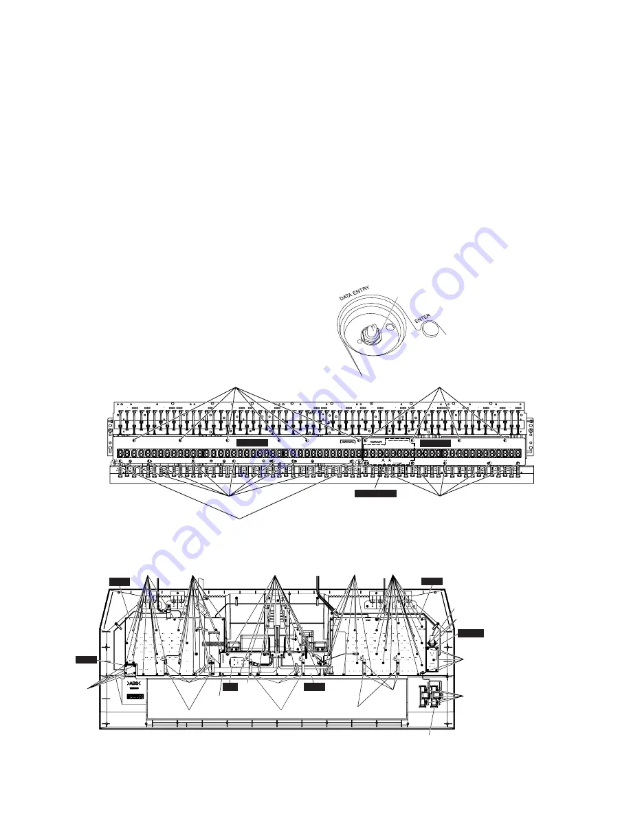
Remove the four (4) screws marked [480A]. The two
panel holders A can then be removed. (Fig.10)
19-3
Remove the twenty six (26) screws marked [480B]. The
PNL circuit board can then be removed. (Fig.10)
*
When installing the PNL circuit board, place the vibra-
tion-proof sheet L in between the circuit board and the
panel buttons.
[480C]
[480C]
Panel Holder B
Panel Holder C
[480C]
[480E]
[470]
[480F-A]
[480F]
[480H]
[480D]
[480D]
[480B]
[480B]
[480G]
[480J]
Power Switch
Panel Holder A
[480A]
PNR
USB
PNL
PNC
EN
MICVR
[480I]
Wheel Assembly
(Fig.10)
Also, place the protection sheet L on the reverse side of
the circuit board. Then, tighten the screws. (Fig.14)
20.
PNR Circuit Board
(Time required: About 7 minutes)
20-1
Separate the unit into the upper case assembly and the
lower case assembly. (See procedure 1.)
20-2
Remove the four (4) screws marked [480C]. The two
panel holders B can then be removed. (Fig.10)
20-3
Remove the twenty six (26) screws marked [480D]. The
PNR circuit board can then be removed. (Fig.10)
*
When installing the PNR circuit board, place the
vibration-proof sheet R in between the circuit board and
the panel buttons.
Also, place the protection sheet L on the reverse side of
the circuit board. Then, tighten the screws. (Fig.14)
[A]
(Fig.13)
[250]: Bind Head Tapping Screw-P 3.0X8 MFZN2B3 (WF266600)
[470]: PW Head Tapping Screw-B 3.0X12 MFZN2W3 (WF002100)
[480]: Bind Head Tapping Screw-B 3.0X8 MFZN2Y (EP600250)
[480]: Bind Head Tapping Screw-B 3.0X8 MFZN2W3 (WE774300)
Содержание 2
Страница 47: ...47 Tyros2 2NA WE84370 2 2 F F to DAC2A CN101 to LCL CN1 to AJK CN7 Pattern Side ...
Страница 57: ...57 Tyros2 Note See parts list for details of circuit board component parts P P Pattern Side 2NA WE81690 4 ...
Страница 61: ...61 Tyros2 Note See parts list for details of circuit board component parts R R Pattern Side 2NA WE81690 4 ...
Страница 64: ...64 Tyros2 Note See parts list for details of circuit board component parts PNR Circuit Board T T ...


