31
01V96 Editor—Owner’s Manual
Meter Window
The Meter window displays the Input, Output, Effect, and Stereo Out meters. To open the Meter win-
dow, choose [Meter] from the [Windows] menu. This window consists of four display pages. You can
access these pages by clicking the tabs along the top of the window.
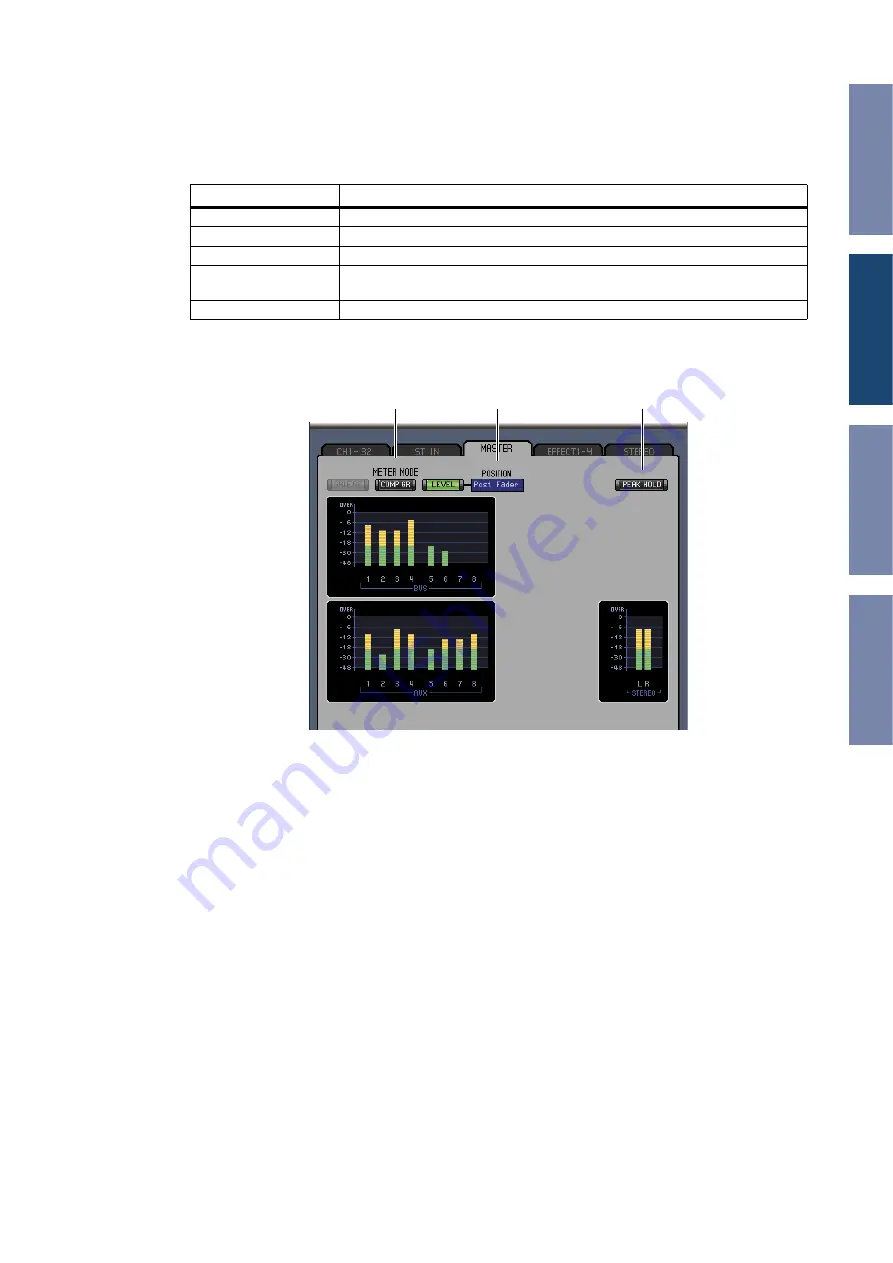
The layout of the Meter window pages is the same regardless of the page selected. (The Master page is
shown below.)
A
Meter mode
You can select the type of meters to be displayed from the following options:
GATE GR:
The meters indicate the amount of gain reduction being applied by the channel Gate.
COMP GR: The meters indicate the amount of gain reduction being applied by the channel
Compressor.
LEVEL:
The meters indicate the channel level.
B
POSITION parameter
This parameter, available only when Meter mode is set to Level, enables you to select the metering
position in the signal path.
C
PEAK HOLD button
This button turns the Peak Hold function on and off.
Page
Function
CH1-32 page
This page displays the Input Channel CH1-32 meters (12 segments).
ST IN page
This page displays the Stereo Input Channel 1-4 meters (12 segments)
MASTER page
This page displays the Bus 1-8, Aux 1-8, and Stereo meters (12 segments).
Effects 1-4 page
This page displays the Channel 1 & 2 input/output meters (12 segments) for Effects
1-4.
Stereo page
This page displays a bar graph (32 segments) of signal levels output to the Stereo Out.
A
2
3


