4
2-2 Taking out/Setting the wasted oil tank
CAUTION
-
Do not exhaust any wasted oil that is handled with this machine to the ground directly. Discard the wasted oil
according to the applicable law and regulations.
-
Be sure to remove the wasted oil upper limit sensor with hands. If you pull it out forcibly, the connector is
damaged and/or the cable is broken.
-
When you set the wasted oil tank, be careful so that any mud or dust cannot be stuck to the hose.
-
Be sure to attach the tank guard onto the machine. Or a new oil pail may fall down and the spilt oil may
contaminate the facility.
1. Remove the tank guard from the rear of the machine, and pull out the hose
from the wasted oil tank.
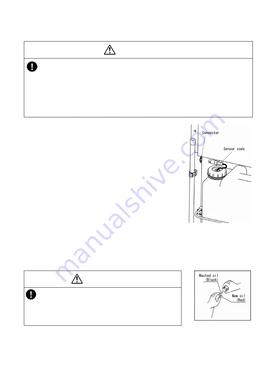
2. Be sure to disconnect the wasted oil upper limit sensor cord from the
connector. (See Fig. 2-2.)
(If you take out the tank although the cord is not disconnected, the cord may
be broken.)
3. Remove the wasted tank cap, and discard the wasted oil into the regulated
wasted oil bath.
4. Set the wasted oil tank onto the machine base, and insert the hose into it.
5. Connect the wasted oil upper limit sensor to the connector.
(When connecting the sensor, face the dowel of the plug located on the edge
of the sensor cord toward the front to set the sensor.)
6. Attach the tank guard onto the machine.
NOTE
The later description of the operation (“If the wasted oil tank is totally full while the machine is operating” on page 17)
allows you to exhaust the wasted oil without taking out the wasted oil tank.
2-3 Connecting the flexible nozzle
CAUTION
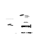
When you connect the nozzle and the hose, do not mistake the hose for
new oil (red) for that for the wasted oil (black) or vice versa. If you do not
connect them correctly, a foreign substance such as dust gets mixed in with
the machine, and it may cause the machine to malfunction. (See Fig. 2-3.)
1.
Pull the outer ring of the coupler located on the hose toward your side.
2. Insert the connector of the nozzle into the coupler, and replace the ring. The connector is fixed.
3. Pull the hose and the nozzle to check to see if they are not disconnected.
Fig.2-2
Fig.2-3


