Yadea C1S Скачать руководство пользователя страница 1

C1S ELECTRIC MOTOR

SERVICE MANUAL

YD1800D-02

General 
Information

Motor

Frame &
Chassis

Electrical
System

Содержание C1S

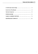
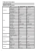
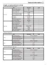
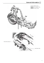
Страница 1: ...C1S ELECTRIC MOTOR SERVICE MANUAL YD1800D 02 General Information Motor Frame Chassis Electrical System...

Страница 2: ......

Страница 3: ...General Information 1 A Few Words About Safety 2 How To Use This Manual 4 Vehicle Information 5 SPECIFICATIONS 6 CABLE HARNESS ROUTING 9 MAINTENANCE SCHEDULE 14...

Страница 4: ...safety and the reliability of the vehicle Any error or oversight while servicing a vehicle can result in faulty operation damage to the vehicle or injury to others Improper service or repairs can cre...

Страница 5: ...elated parts carelessly When performing the vehicle maintenance be sure to wear safety protective gears and use insulation tools Always check the safety protective gears and insulation tools for damag...

Страница 6: ...llow instructions You CAN be KILLED or SERIOUSLY HURT if you don t follow instructions You CAN be HURT if you don t follow instructions Instructions how to service this vehicle correctly and safely As...

Страница 7: ...aurora white deep water blue liquid silver electro optic bright red interstellar brown Configuration category Braking method Battery capacity Power off switch Basic configuration All disc brake 60V30...

Страница 8: ...tire brand Zhengxin Zhengxin Front brake Hydraulic single disc Hydraulic single disc Rear brake Hydraulic single disc Hydraulic single disc Caster angle 23 23 Trail length mm 75 75 MOTOR Motor model...

Страница 9: ...2 26 2 2 01 Travel K1 mm Travel K2 mm K1 50 K2 30 Rear fork oil capacity ml 76 2 5 Suspension method Integrated swing arm HYDRAULIC BRAKE type 1 ITEM STANDARD LIMIT Front Specified brake fluid DOT 3 o...

Страница 10: ...tightening torque Fastener name Thread diameter Tightening torque N m Note 6 8 6 8 8 8 Bolts and nuts M4 2 3 2 3 M5 3 5 6 4 7 M6 6 9 7 11 M8 16 21 18 25 M10 28 36 30 40 M10 1 25 32 40 35 45 M12 42 52...

Страница 11: ...ing amount of the cable ties is 3 5mm Cable tie fixing Wire clamp fixing Distribution valve Rear brake oil pipe Brake oil pipe to the front caliper Central controller USB connection Brake oil pipe to...

Страница 12: ...combination switch cable Fix the L R combination switch and brake switch to the stay on the handle pipe Four holes throttle grip Six hole black right combination switch Left brake disconnect wire Left...

Страница 13: ...General Information 11 Cable tie fixing Wire clamping fixing Wire hook fixing Side stand switch wire Seat Zipper Cable...

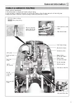
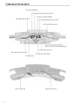
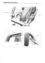
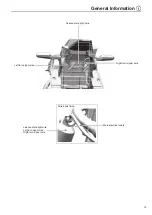
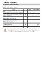
Страница 14: ...General Information 12 Rear brake oil pipe Motor line Motor line Motor line...

Страница 15: ...eneral Information 13 Left turn signal wire License plate light wire Right turn signal wire Main electrical cable Wire hook fixing License plate light wire Left turn signal wire Rigth turn signal wire...

Страница 16: ...ether the tire is worn 4 Whether the light bulb is on 5 Whether the brake pad is worn 6 Whether the rim is deflecting or deformed 7 Whether the front fork of the frame is deformed 8 Whether the fasten...

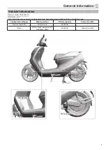
Страница 17: ...Motor 15 Installation and disassembly 16 Fault diagnosis and maintenance 17 Tools for reparing 18...

Страница 18: ...st Page 27 Foot pedal Page 25 Side cover Page 28 Operating order Operating name parts number Number Note 1 Hexagon flange bolts M8 35 1 Separate the rear fork from the rear swing arm 2 Hexagon flange...

Страница 19: ...itch Turn off the power switch and use the multimeter diode position to check whether the P position switch is normal NO switch of parking switch failure YES 2 Check the brake power switch Turn off th...

Страница 20: ...or reparing Tool name Number Application Gloves A pair Wear the motor and motor controller during operation Wrench One set Disassembly and use of nuts and bolts Torque wrench One set Pre tightening of...

Страница 21: ...Front Shock Absorber 34 Steering Stem 36 Rear Shock Absorber 37 Steering Assembly 38 Braking System 39 CBS 43 The steps described in this chapter are all disassembly steps and the installation steps c...

Страница 22: ...Front Wall Page 21 9 Rear Side Strip L R Page 27 3 Front Inner Cover Frame Chassis Page 22 10 Center Cover Page 27 4 Toolbox Page 23 11 Rear Handrail Page 28 5 Front Cover Page 24 12 Rear Inner Cover...

Страница 23: ...Frame Chassis 21 1 Front Fender Pan head hexagon step bolt 10x4 M6x10 2 Front Wall Tapping clip ST4 8 Cross recessed pan head tapping screw ST4 8x16 Cross recessed pan head tapping screw ST4 8x16...

Страница 24: ...e bolt combined with flat washer M6x12 Cross recessed flat head slotted tapping screw ST4 2X13 Cross recessed flat head slotted tapping screw ST4 2X13 Front Wall Page 21 Luggage Box Seat Page 26 Rear...

Страница 25: ...with flat washer M6x20 Cross recessed flat head slotted tapping screw ST4 2X13 Front Wall Page 21 Cross recessed flat head slotted tapping screw ST4 2X13 Cross recessed flat head slotted tapping screw...

Страница 26: ...Bucket Components 1 3 Charging Port Cover 1 4 Hook 1 5 Front Cover Cross recessed pan head screw ST4 8x16 Cross recessed pan head tapping screw ST4 2x13 Operation Order Operation Name parts Name Quan...

Страница 27: ...edal installation bolt M6 16 4 3 Foot pedal assembly including flip hinge lithium battery cover lithium battery opening rocker 1 When installing please proceed in the reverse order of disassembly the...

Страница 28: ...the key opens the battery compartment cover as shown 2 Lithium battery compartment open cable 1 3 Seat Bucket 1 Remove part 3 to take out the seat bucket and seat combination 4 Lithium Battery Lock 2...

Страница 29: ...p screw M8x20 5 Cross recessed pan head tapping screw ST4 2 13 Cross recessed pan head tapping screw ST4 2 13 Cross recessed pan head tapping screw ST4 8x16 Other Seat Seat Bucket Page 26 Operation Or...

Страница 30: ...head slotted tapping screw ST4 2x13 Cross recessed pan head tapping screw ST4 8x13 Cross recessed flat head slotted tapping screw ST4 2X13 11 Rear Handrail Hexagon flange bolt M8x25 Seat Page 26 Rear...

Страница 31: ...Frame Chassis 29 12 Rear Inner Cover Hexagon flange bolt combined with flat washer M6x16 Cross recessed pan head tapping screw ST4 8x13...

Страница 32: ...Frame Chassis 30 13 Rear Fender Hexagon socket flat round head flange screw M8x12 Hexagon flange bolt big head M6x12 Hexagon flange bolt combined with flat washer M6x12 14 Rear View Mirror...

Страница 33: ...me Chassis 31 Frame Body Stay 1 Side Stay 2 Main Stay 1 1 1 Hexagon flange bolt M10 1 25 30 Hexagon flange locking nut M10 1 25 Align the spring up and down with the corresponding groove of the main s...

Страница 34: ...Front wheel shaft sleeve right 20 12 34 Operation Order Operation Name parts Name Quantity Note 1 Oil seal 20x32x5 1 When disassembling please proceed in the following order When installing please pr...

Страница 35: ...tandard part 2 Oil Seal 2 3 Bearing 2 4 Spacer Sleeve 1 Use a normal bearing extraction tool to remove the bearing Use lithium grease for lubrication Service Tools Tools Name Quantity Application Lock...

Страница 36: ...bsorber Composition of Front Shock Absorber Hexagon flange bolt big head Combined with wash and flat washer M8x35 Hexagon socket bolt M8x40 1 Front Fender Page 22 Front Wall Page 21 Loosen the lower s...

Страница 37: ...not be disassembled and repaired to avoid affecting the performance If any damage to the front shock absorber is found or the smooth operation is not possible please go to the Yadea dealer for inspect...

Страница 38: ...is aging or polluted black replace After confirming that the parts are intact raise the front shock absorber assembly and tighten the lock nut 1 Check the rotation flexibility if not flexible Loosen t...

Страница 39: ...ens Damaged main spring Rear shock absorber hardens Damaged main spring b Maintenance 1 Open the seat cushion flip 2 Remove the seat bucket 3 Inspection Lock bolt for rear shock absorber Loosen Tighte...

Страница 40: ...Frame Chassis 38 Steering Assembly Align Align 1 1 When installing the brake pump make sure that the UP mark is facing upward Align the edge of the brake pump with the engraved mark on the handlebar...

Страница 41: ...parts Name Quantity Note 1 Main Pump 1 2 Main Pump Fixing Base 1 3 Main Pump Fixing Base Bolt 2 4 Brake Handle 1 5 Brake Handle Mounting Bolt 1 6 Nut 1 7 Switch Mounting Screw 1 8 Brake Switch 1 9 Oil...

Страница 42: ...1 2 Dust proof Robber Ring 1 3 E shaped Retaining Ring 2 4 Main Pump Thruster Components 1 5 Spring 1 6 Oil Level Sight Glass 1 7 O shaped Rubber Ring 1 When installing please proceed in the reverse o...

Страница 43: ...Frame Chassis 41 Disassembly of brake components caliper body part 2 2 1 12 12 11 1 10 9 8 6 2 5 5 7 10 12 3 4 3 Abrasion warning slot...

Страница 44: ...e the front wheel solidity limit Vertical 1 0mm Horizontal 1 0mm Trouble Check for Brake Failure Number Possible cause of failure Repair method Note 1 Worn brake pads Replacement beyond wear limit 2 W...

Страница 45: ...front caliper oil pipe rear caliper oil pipe and CBS distribution valve The left and right brake oil pipes need to be caught in the wire hoop of the frame The front caliper oil pipe needs to be wound...

Страница 46: ...When the meter fault light is on if the brake handle is not reset when power is turned on confirm whether the brake handle is stuck If there is any remove the stuck foreign object and then power on a...

Страница 47: ...Frame Chassis 45 Front brake oil pipe Rear brake oil pipe Wiring diagram of front and rear brake oil pipe of vehicles without CBS...

Страница 48: ...MEMO...

Страница 49: ...tem 47 System Overview 48 Meter 50 Lighting System 52 Combination Switch Handle 59 Battery 61 Charger 63 Converter 65 Controller 67 Central Controller 70 Electrical components 73 Power Lock 76 Remote...

Страница 50: ...Electrical System 48 System Overview Location of Electrical Components GPS Instrument Handle Converter Horn Battery Central controller Charge fuse Controller Air switch...

Страница 51: ...Page 67 Is the controller normal No Faulty controller Yes 3 Brakelight switch Inspection Check the brakelight switch Is the brakelight switch normal No Faulty brakelight switch Yes 4 Throttle handle...

Страница 52: ...up please combine the following fault phenomena to determine the body failure parts Phenomenon Body faulty parts No power output when turning the handle Faulty handle No power output when turning the...

Страница 53: ...horn The brake light is off Faulty brake light Connector Definition Connector PIN location Name Explanation AMP174973 2 Board end 3 GND Power battery negative electrode 60V Li ion battery 2 CHARGE IN...

Страница 54: ...tapping screws ST4 8x16 All Low beam light area Diagram of external wire harness of the headlight shell High beam light area Position light light area High beam Blue Front position light Brown Positi...

Страница 55: ...right turn signal License light Brown Position Diagram of license light wire Black Positive Cross recessed pan head tapping screws ST4 2x13 Black 12V Black 12V Right blue Negative electrode Left orang...

Страница 56: ...front turn signal check the left front turn signal end wire and replace the central control 3 Replace the central control 4 Replace the left front turn signal and replace the central control Faulty l...

Страница 57: ...urn signal end wire and replace the central control 3 Replace the central control 4 Replace the left rear turn signal and replace the central control Faulty right rear turn signal 1 Press the right tu...

Страница 58: ...f or AUTO mode is on and during daytime short press the headlight button the headlight does not light the meter has no fault reminder and connect the Yadea APP and the fault detection shows that the l...

Страница 59: ...trol Faulty position light and license light 1 Either the position light or license light does not light before or after power is on or none at all 2 The position light and license light light after p...

Страница 60: ...n shows the horn is faulty 4 The horn always lights when the power is on and also rings during fault detection 1 The central control does not receive the horn button signal 2 The central control judge...

Страница 61: ...MODE Black Yellow Double flash Left combination switch Green Ground Light green Horn Blue High and low beam Light blue Right turn White Brown SET Orange Left turn Connector DJ7061 2 3 21 Handle Right...

Страница 62: ...nd there is no power output when turning the handle 1 Check the connection status of the turnout lead wire Check if the wire is loose 2 Check the status of the Hall handle Use a multimeter to measure...

Страница 63: ...ery you need to rotate the door lock to the seat cushion open position open the seat cushion and turn off the air switch 1 Rotate the electric door lock to the open position of the battery box cover a...

Страница 64: ...of battery protection board 1 Use under the ambient temperature conditions allowed by the battery 2 After sales outlets for battery testing Charge over temperature protection 1 The vehicle is powered...

Страница 65: ...it Negative short circuit N Blue AC Null line L Brown AC Live line Ground Yellow Green Ground R E D V L N TY 013 TOONY YEAN R 16A 250V SUO4039 4005C B direction C direction A direction LED LAMP Judgem...

Страница 66: ...f the wire Mains power socket inspection the input plug has no signs of ablation and there is no abnormality in the plug contact Yes 1 If the output plug is damaged stop using it and replace the charg...

Страница 67: ...the entire vehicle and float charging for auxiliary batteries Hexagon flange bolt big head M6x12 Front Wall Page 21 Judgement method for fault maintenance of Converter failure Common faults no output...

Страница 68: ...lity OK Abnormal Replace maintenance wires and connectors 3 Output voltage inspection Connect the converter well open the electric door lock and use a multimeter DC voltage file to check whether there...

Страница 69: ...not run the loud abnormal noise the motor is unable to rotate cannot be loaded the slow speed the stuck driving and the electric vehicle is locked when pushing Steps for troubleshooting Connector PIN...

Страница 70: ...ll cause the motor to rotate without alarm inclination or vibration will still alarm Troubleshooting This signal is the motor phase line voltage signal transparently transmitted by the controller If t...

Страница 71: ...o voltage output after removing external influences please replace the controller Hall Power Positive electrode of Hall Negative electrode of Hall 5V Multimeter is placed in DC voltage range Test meth...

Страница 72: ...Control and receive the signal of each key lever device of the combination switch Hexagon flange bolt big head M6x20 J3 connector definition J4 connector definition Pin number Signal description Pin...

Страница 73: ...served 20 Iron Horn External DC12V 20 Reserved 21 Faucet lock solenoid valve 21 Reserved 22 Ground 22 Meter 23 Ground 23 GND 24 Ground 24 485A 25 Ground 25 485B 26 Ground 26 Seat lock switch signal re...

Страница 74: ...he controller s control signal 1 Try to release P after side stand is on 2 Replace the right combination switch check the P gear button to the central control line check the vehicle s 485 communicatio...

Страница 75: ...on tool to remove the bearing Horn Function definition It is to convert the 12V electric signal into sound to warn pedestrians and other vehicles to draw attention and ensure driving safety 1 Hexagon...

Страница 76: ...emove the horn open the electric door lock and use the multimeter DC voltage to check whether the input end of the horn connector is 12V voltage input when pressing the horn button No 12V output 1 Che...

Страница 77: ...Electrical System 75 GPS Front Wall Page 21...

Страница 78: ...System 76 Power Lock Function definition The components that realize the switch and anti theft function of electric vehicles 1 Hexagon flange bolt small head M6x16 Front Wall Page 21 Align the pin wit...

Страница 79: ...e that it is OK 3 Battery input voltage inspection Turn off the electric door lock use a multimeter DC to measure that there should be a 60V DC voltage input between the red wire and the ground No 1 C...

Страница 80: ...Indication Judge that the remote control is OK 2 Remote controller pairing method When the mechanical key is in the OFF state the electric door lock is turned on and off 5 times and the 5th time stays...

Страница 81: ...5mm 100mm pc 1 3 Open end wrench 8 10 set 1 12 14 13 16 14 17 17 19 22 24 4 Double offset ring spanner 8 10 set 1 12 14 13 16 14 17 17 19 22 24 5 Adjustable spanner 10 inches pc 1 15 inches pc 1 6 Al...

Страница 82: ...rench 55 62 pc 1 13 Front shock absorber lengthened octagonal sleeve 32 45 pc 2 45mm 32mm 14 Socket ratchet wrench and socket 1 2 260mm with various specifications sleeve set 1 15 Electric iron 40W pc...

Страница 83: ...er Code C2016708000 Code C1059754000 Code C2016709000 Code C1059755000 Code C1059756000 Name Battery box Name Front left side stripa Name Front right side strip Name Rear left side strip Name Rear rig...

Страница 84: ...eft shock absorber Code L3070001070 Code L3230000393 Code L3220000412 Code L3210000886 Code L3200150240 Name Front right shock absorber Name Rear handrail Name Main pedal rubber Name Side pedal rubber...

Страница 85: ...t turn signal Name Intelligent central control with GPS Name Left combination switch Code L7110000134 Code L7030000571 Code L7040000567 Code L1360100015 Code L1060150338 Name Right combination switch...

Страница 86: ...switch Green yellow Iron horn Instrument indicator Communication line A Cruise control switch Communication line B 20A Front left turn signal Rear left turn signal Front right turn signal Rear right t...

Страница 87: ......

Страница 88: ...2020 06 29 The first revision...

Отзывы: