I/O and Cabling Considerations
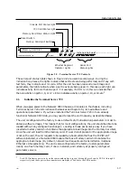
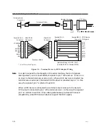
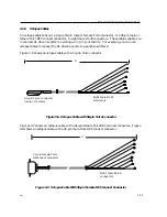
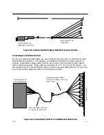
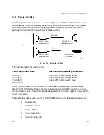
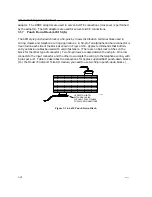
If you want to connect to another DTE device, you will need a crossover wiring scheme
somewhere in the cabling. (Communication between DTE-to-DTE devices requires a
crossover.) To make a modular cable with a crossover, you need only crimp the RJ-45
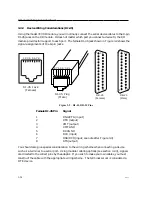
connector in the same direction at both ends. This crosses all wires in the cable. Figure 3-3
shows the crossover wiring scheme. Typically, to connect a standard terminal to a serial port
you would use a crossover cable with female DB-25 adaptor at the terminal end.
The crossover connects the terminal server transmit data (XMT) line to the receive data (RCV)
line of the user DTE device. Similarly, the terminal server receive data (RCV) line crosses
over to the transmit data (XMT) line of the user DTE device. The other signals are crossed
over in a similar manner (see Figure 3-3).
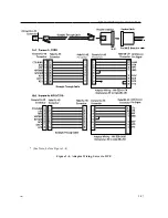
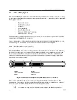
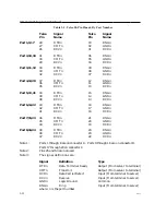
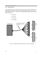
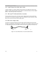
If you want to connect a DCE device to a terminal server serial port, straight-through wiring is
required. To make a modular straight-through cable, you need only crimp the RJ-45 connector
in opposite directions at both ends. Figure 3-4 shows the straight-through wiring scheme.
3.2.3
Modular Adaptors (RJ-45 to DB-25)
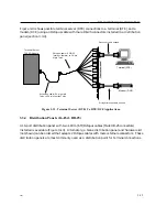
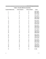
You can obtain adaptors with male and female DB-25 connectors from Xyplex. These adaptors
direct signals from the RJ-45 connector on the cable to the correct pin on the DB-25 connector.
Figures 3-3 and 3-4 show how devices are cabled when you use these adaptors.
Flow Control and Modem Control
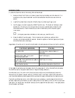
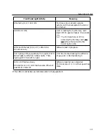
The model 721 20-port I/O module's serial ports can be set up to support RTS/CTS flow control,
modem control, or both of these concurrently. Section 5.6 of the Software Management Guide
describes flow control options and explains how to set up flow control at a port. The adaptors
shown in Figures 3-3 and 3-4(b) support RTS/CTS flow control. Terminal Server 720 RJ-45
serial ports can also be set up to support modem control. Section 5.5 of the Software
Management Guide describes modem control options and explains how to set up modem
control at a port. The adaptor shown in Figure 3-4(a) supports modem control, by supporting the
RING signal.
0021
3-25

