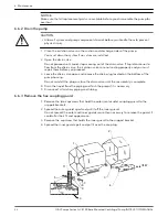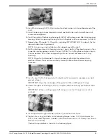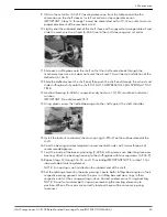
20.Install a new 1/64 in thick gasket with a light coat of commercial cup grease on both
gasket surfaces.
IMPORTANT: Align the inner edge of the gasket with the stuffing box O-rings.
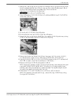
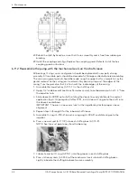
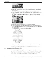
21.Lower the upper half casing (2–001–7) into place and install casing joint bolts (2–904–1
and –2).
IMPORTANT: When installing upper half casing, assure that O-rings are not cut or
pinched.
22.Insert tapered casing joint dowels (2–916–1), and drive them home.
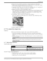
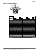
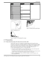
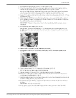
23.Tighten the casing joint bolts to the following torque values: 140 ft-lb minimum for
5/8”-11 hex head capscrews (Grade 5); 350 ft-lb minimum for 7/8”-9 Ferry Cap Countr-
bor screws (Grade 8).
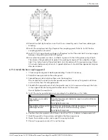
The bolt torque pattern is shown in the following figure.
24.Rotate the shaft by hand to assure that it turns smoothly and is free from rubbing or
binding.
25.Install the coupling and align. Replace the coupling guard. Refer to Install the hex
coupling guard instructions.
6.9.3 Reassemble the pump with packing
All bearings, O-rings, seals, and gaskets should be replaced with new parts during
assembly. All reusable parts should be cleaned of all foreign matter before reassembling.
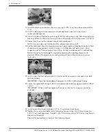
The main casing joint gasket should be made using the upper half as a template. Lay the
gasket material on the casing joint and mark it by pressing it against the edges of the
casing. Trim the gasket so that it is flush with the inside edges of the casing.
6 Maintenance
46
G&L Pumps Series A-C 8100 Base Mounted Centrifugal Pump INSTRUCTION MANUAL
Содержание G&L A-C 8100 Series
Страница 1: ...INSTRUCTION MANUAL AC5659D G L Pumps Series A C 8100 Base Mounted Centrifugal Pump...
Страница 2: ......

