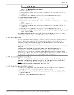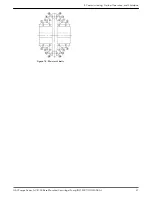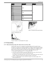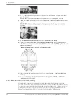
1. Outer guard
2. Inner guard
3. Attach the support bracket inline with the bolt
4. Support bracket
5. Nut
6. Lockwasher
7. Capscrew
8. Flat washer
9. Spacer washer
10.Option used instead of the spacer where overall guard length exceeds 12 in. (30 cm) or
the guard width is over 10 in. (25 cm) across the flats
11.Locate the support arm between the outer guard ends. Align the arm with holes in the
outer guard and holes in the saddle bracket.
12.Motor saddle bracket attached to the motor saddle
Figure 19: Hex guard exploded view for typical installation
6.6.4 Disassemble the pump with mechanical seal on the shaft
1. Close valves on suction and discharge sides of pump.
If no valves have been installed, it will be necessary to drain the pump.
2. Remove coupling guard and disconnect coupling.
Refer to instructions on how to remove the hex coupling guard.
a) Remove external tubing, if supplied.
3. Loosen but do not remove main joint capscrews (2–904–1 and 2–904–2). Insert a
screwdriver or pry bar into the slots between the upper and lower casing halves —
separate joint.
4. Remove all casing main joint capscrews and dowels (2–916–1). Lift off the upper casing
half.
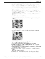
5. Tap the stuffing boxes with a soft-headed hammer to break the seal between the
stuffing box and lower casing half, and lift the rotating element out of the lower casing.
A spare rotating element can be installed at this point.
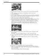
6. Remove the four capscrews (3–904–9) from each bearing housing (3–025–3 and 3–025–
4) and remove the bearing housings from the shaft.
7. Remove the snap ring (3–915–4) (or locknut and lockwasher on pumps built after 1991)
from the outboard end of the shaft and, using a puller, remove the bearing (3–026–4)
from the shaft. Remove the drive end bearing in the same manner.
Snap ring is not used on drive end bearings.
IMPORTANT: Do not reuse the ball bearings.
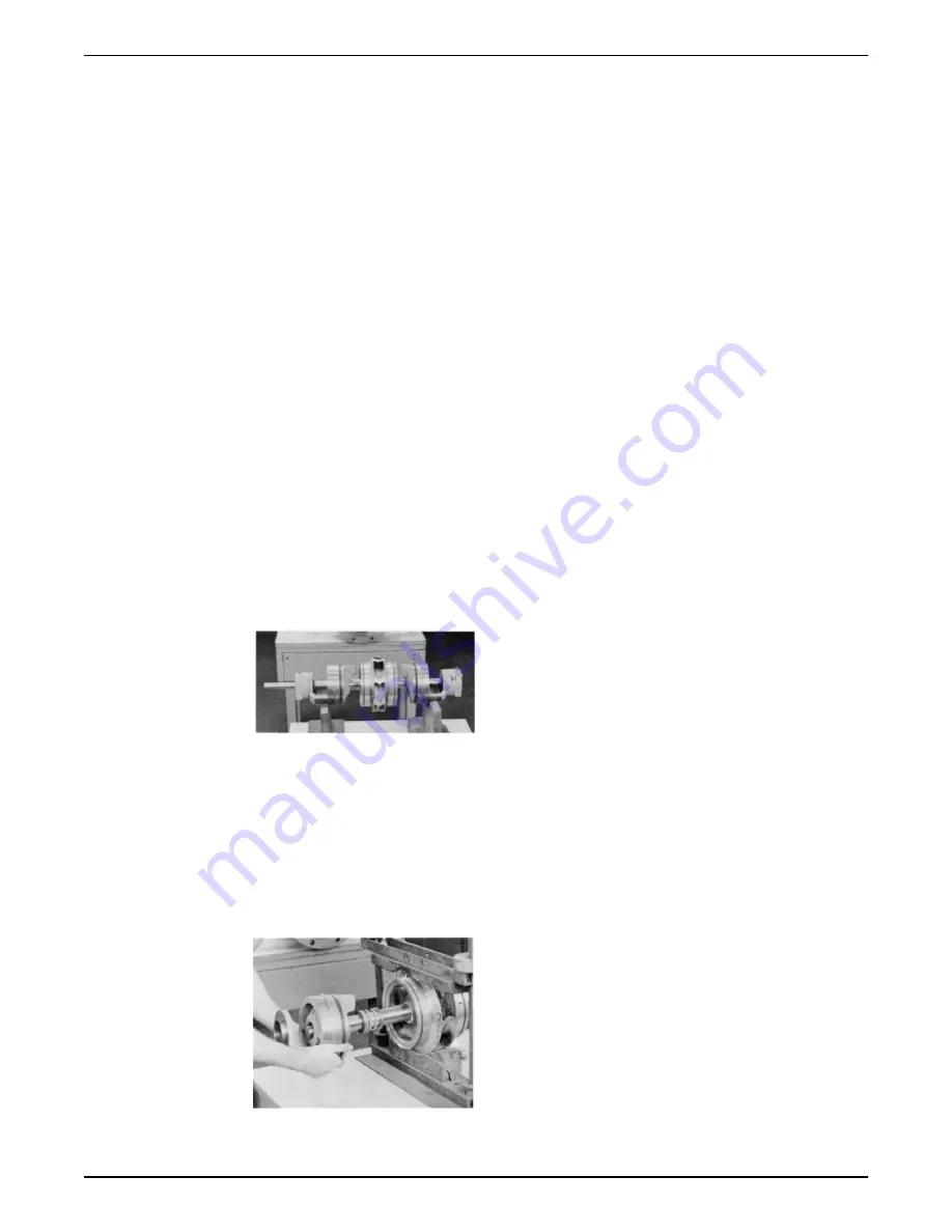
8. Slide stuffing boxes (3–073–9) off of the shaft, working deflector ring (3–136–9) off the
shaft at the same time.
9. Drive oil seal (3–177–9) from the stuffing box.
10.Drive mechanical seal seat (3–401–0) from the stuffing box.
6 Maintenance
G&L Pumps Series A-C 8100 Base Mounted Centrifugal Pump INSTRUCTION MANUAL
33
Содержание G&L A-C 8100 Series
Страница 1: ...INSTRUCTION MANUAL AC5659D G L Pumps Series A C 8100 Base Mounted Centrifugal Pump...
Страница 2: ......

