


8. Install the entrance cover and the O-ring on the stator housing.
9. Fasten the screws on the entrance flange so that the cable insertion assembly bottoms
out.
10.Connect the SUBCAB cable phase leads to the starter equipment according to the
11.Perform the system setup by using the Setup wizard and other commissioning
procedures in the chapter “System Setup” in the SIO Manual for the MAS 801.
12.Insulate the unused T3, T4 leads.
Insulating the unused T3, T4 leads is preferable to clipping them off. If the T1, T2 leads
become damaged, then the T3, T4 leads can be used instead.
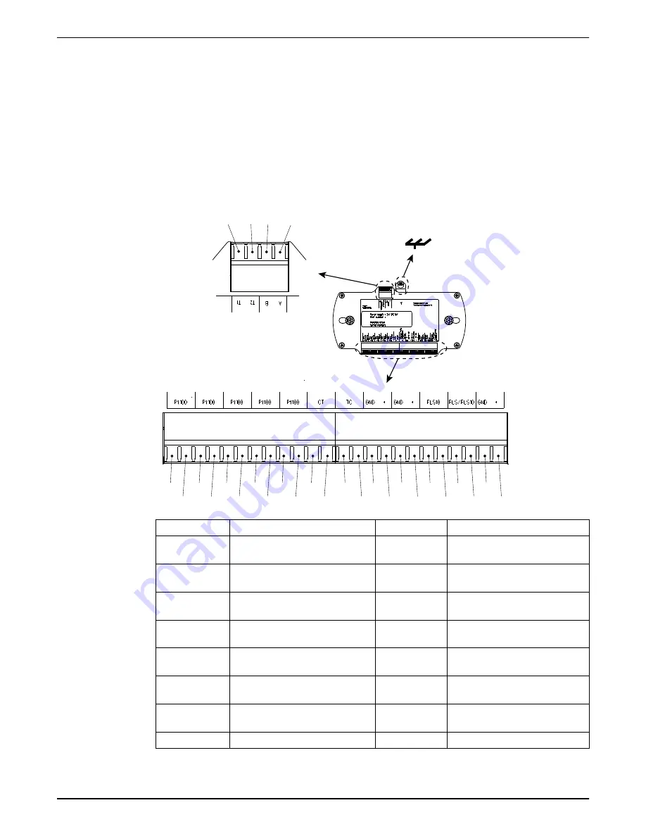
4.6.5.1 Terminals used in standard applications
51
63
81
80
24
23
22
21
20
19
4
3
38
37
11
12
13
14
1
2
9
10
34
33
17 18
16
15
WS008193B
Terminal
Description
Terminal
Description
37, 38
Temperature support bearing,
Pt100
13, 14
Analog input 0/4 -20 mA,
+12 VDC, GND
3, 4
Temperature main bearing, Pt100 1, 2
Leakage: Inspection chamber or
stator housing, FLS/FLS10
19, 20
Temperature stator winding 1,
Pt100
9, 10
Leakage, junction box: FLS/
FLS10
21, 22
Temperature stator winding 2,
Pt100
34, 33
Leakage, inspection chamber:
FLS10. Water in oil: CLS
23, 24
Temperature stator winding 3,
Pt100
15
T1 power supply and
communication
80, 81
Pump current, CT
16
T2 power supply and
communication
51, 63
Temperature stator winding:
Thermal contact or thermistor, TC
17
Not used
11, 12
V
out
+12 VDC, GND
18
Not used
4.6.6 Connect the cables: Ex-proof pumps with MAS 801
4 Installation
42
P7030, P7035, P7040 Installation, Operation, and Maintenance Manual
Содержание FLYGT P7030 Series
Страница 1: ...Installation Operation and Maintenance Manual 882901_15 0 P7030 P7035 P7040...
Страница 2: ......


