background image


https://www.XPOtool.com 


Item 60910


Page 9 


The Tool Experts


04 2022-1


6

th

 step: adjustments


After having finished the above-mentioned steps, the following steps do not need to be followed. They 
are necessary in case the individual parts do not properly match. To operate this spreader, push the 
handle  up.  You can shift  the position  of the wing  nut on the pressure  gauge  and lever to adjust the 
spacer of the three holes between the hopper and adjustable plate according to your needs.


Set  the  steel  wire  into  the  small 
hole.


To operate this spreader, push the handle all 
the way up to the highest position.


Push  the  handle 
alle  the  way  down. 
Use it to adjust the 
adjustable  plate  so 
that the hole on the 
hopper  bottom  ex-
actly  matches  the 
holes on the adjust-
able plate.


Untighten  and  re-
move  both  bolts. 
Re-insert  them  af-
ter  modifying  the 
adjustments.


The  drive  wheel  should  turn  in 
the  direction  shown  while  the 
spreader in pushed forward.


Содержание GT1507

Страница 1: ...ary depending on model Please read and follow the operating instructions and safety information prior to initial operation Technical changes reserved Illustrations functional steps and technical data...

Страница 2: ...you have found an error or wish to suggest an improvement we look forward to hearing from you Send us an e mail to service wiltec info or use our contact form https www wiltec de contacts The most re...

Страница 3: ...adcast Always wear eye and hand protection while handling and broadcasting lawn or garden chemi cals Never operate the tractor or spreader without wearing solid shoes and do not let anyone ride or sit...

Страница 4: ...washer 6 4 3 Bolt M6 35 4 9 Washer 16 1 4 Hexagon socket screw 1 10 End cap 2 5 Fillister head screw M4 20 1 11 Inner axle bearing 2 6 Counter nut M6 12 12 R pin 1 Assembly instructions 1st step 1 Mo...

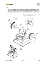
Страница 5: ...t the hole on the driving axle is on the right as shown 3 Fix the mounting frame and foot to the hopper with M6 40 screws M6 counter nuts and big washers 6 Note The screws and nuts do not need to be t...

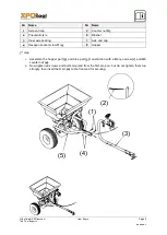
Страница 6: ...connecting plate 5 to the wheel frame with a M6 35 screw 4 and M6 counter nut 3 2 Then mount the connecting rod to the wheel frame with a M6 60 screw 7 and M6 counter nut and fix the connecting plate...

Страница 7: ...onstruction to the right axle with the M5 45 hexagon socket screw and M5 counter nut then mount the end cap on the right axle with a wooden or rubber mallet 3 Now mount the left wheel construction to...

Страница 8: ...Inner axle bearing 7 Axle end cap 4 Hexagon socket screw M 45 8 Hopper 5th step 1 Assemble the hopper part 5 and tube part 3 construction with a M6 40 screw 1 and M6 counter nut 4 2 Now tighten all sc...

Страница 9: ...nd lever to adjust the spacer of the three holes between the hopper and adjustable plate according to your needs Set the steel wire into the small hole To operate this spreader push the handle all the...

Страница 10: ...https www XPOtool com Item 60910 Page 10 The Tool Experts 04 2022 1 Exploded view...

Страница 11: ...38 Outer axle bearing 2 13 R pin 1 39 Driving and axle assembly 1 14 Bolt M6 40 10 40 Screw M4 20 1 15 Fixed plate 1 41 Big washer 6 5 16 Screw M5 12 4 42 Nylon washer 1 17 Adjustable plate 1 43 Conn...

Отзывы: