xcore.ai Multichannel Audio Board 1v1 Hardware Manual
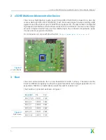
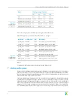
Board Net
xCORE GPIO
Port
Description
X_DAC_D0
X1D39
P1P0
Serial data output 0 (I2S or TDM)
X_DAC_D1
X1D38
P1O0
Serial data output 1 (I2S or TDM)
X_DAC_D2
X1D37
P1N0
Serial data output 2 (I2S or TDM)
X_DAC_D3
X1D36
P1M0
Serial data output 3 (I2S or TDM)
DAC_MUTE_N
X0D16
P4D0
Output to mute audio when low
LRCK
X1D01
P1B0
Serial left/right frame clock
BCLK
X1D10
P1C0
Bit clock for serial data transfer
MCLK_DAC
See note
NA
Buffered global audio master clock
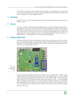
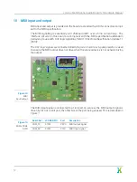
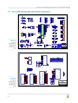
Figure 9:
Analog output
xCORE GPIO
8
Digital audio output
Optical and coaxial digital audio outputs are provided. Both of these outputs can support
transmission of audio data in IEC60958 consumer mode (S/PDIF) format. This format
allows transmission of two channels of audio data at up to 192kHz. Note the optical
transmitter used on the board can only support up to 96kHz in this mode.
Additionally the optical output can transmit data in the ADAT optical format. This format
allows transmission of eight channels of audio data at 48kHz. The S/MUX extension to
ADAT allows four channels at 96kHz or two channels at 192kHz.
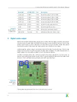
In order to reduce clock jitter on these outputs, the data outputs from xcore.ai are re-
clocked using the global audio master clock to synchronise the data into the audio clock
domain. This is achieved using simple external D-type flip-flops.
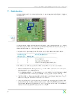
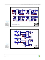
Figure 10:
Digital audio
output
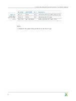
The signals are generated from two 1-bit ports on xcore.ai.
9


