Virtex-6 FPGA System Monitor
57
UG370 (v1.1) June 14, 2010
Application Guidelines
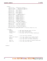
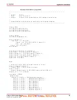
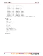
Simulation of the SYSMON Design
A behavioral simulation model is provided for the Virtex-6 FPGA System Monitor. This
model allows the user to simulate most of the System Monitor functionality and timing.
The simulation model also allows users to easily introduce analog signals into their design
without the need for mixed mode or analog simulation capability in their tools. This is
achieved by the use of a stimulus file. In the example instantiation above a parameter
SIM_MONITOR_FILE was added for this purpose. The parameter points to the stimulus
file that is the source for the analog signals introduced into the simulation. In this example,
the stimulus file is called
vccaux_alarm.txt
. The stimulus file is a text file that uses a
very simple format for setting up analog input values (for example, volts and temperature)
and timing information (the format is shown below). The first column must contain the
timing information and analog input information is recorded in the next columns.
Columns must have a valid header that indicates the input channel or source of the analog
signal (for example, V
CCAUX
, TEMP etc.). The column order for the analog input channels
is not important, and unused inputs need not be recorded in the stimulus file. Each row
corresponds to the time stamp in the first column. Thus, in the example below, at 5 µs, the
temperature is set to 85°C, V
CCAUX
is set to 2.45V, V
CCINT
is set to 1.1V, etc.
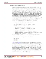
// Must use valid headers on all columns
// Comments can be added to the stimulus file using ‘//’
TIME
TEMP VCCAUX VCCINT VP
VN
VAUXP[0]
VAUXN[0]
00000
45
2.5
1.0
0.5
0.0
0.7
0.0
05000
85
2.45
1.1
0.3
0.0
0.2
0.0
// Time stamp data is in nano seconds (ns)
// Temperature is recorded in °C (degrees centigrade)
// All other channels are recorded as V (Volts)
// Valid column headers are:
// TIME, TEMP, VCCAUX, VCCINT, VP, VN,
// VAUXP[0], VAUXN[0],...............VAUXP[15], VAUXN[15]
// External analog inputs are differential so VP = 0.5 and VN = 0.0 the
// input on channel VP/VN in 0.5 - 0.0 = 0.5V
For this example, the stimulus file
vccaux_alarm.txt
contents are shown below:
//Test alarm feature on SYSMON.
//Vccaux moves outside upper limit after 20us
TIME
VCCAUX
00000
2.50
20000
2.80
60000
2.50
and
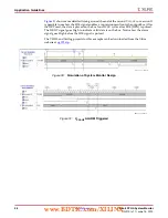
show the output of a simulation using the analog stimulus file
shown above. In
, two passes through the sequence can be clearly seen. The first
conversion in the sequence is the calibration channel. This conversion is 15.6 µs long and is
due to the generation calibration of the calibration coefficients, three separate conversions.
The second conversion is 5.2 µs and is the conversion on the V
CCAUX
sensor channel. The
result of the conversion on the V
CCAUX
channel is enabled on to the output bus shortly
after BUSY goes Low. A result of
0x355
is recorded, which represents 2.5V. The analog
stimulus file changes the V
CCAUX
level to 2.8V at 20 µs. This new value for V
CCAUX
is
sampled when BUSY goes High at the start of the next conversion on V
CCAUX
. The output
bus changes to
0x3BB
at the end of the conversion when BUSY goes Low. The value
0x3BB
is equivalent to 2.8V. The Alarm signal also goes High around the end of this conversion to
indicate the result is outside the user-specified limits.
www.BDTIC.com/XILINX


