background image

XCT80 Truck Crane Operation Manual  

9-14

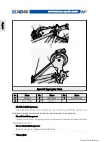
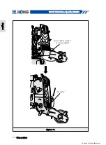
Figure9-15 Transformation of mounting angle adjustment from 0

°

to 30

°

2. Transformation from 0

°

to 30

°

as shown in 

gure9-15

Remove  the  lifting  wire  rope  rigging  of  the  auxiliary  winch  from  the  auxiliary  hook,  tie  the 

auxiliary  hook  rigging  and  the  auxiliary  arm  head  with  the  discoloration  cotton  lifting  rope  in  the 

spares  and  confirm  it  is  firm. Then  slowly  lift  the  auxiliary  winch,  make  the  auxiliary  winch  lifting 

rope in tension state, pull out the pin axle of the 15

°

 mounting hole on the luf

ng pulling plate, and 

then  slowly  lower  the  auxiliary  winch  wire  rope  to  30

°

  installation  angle  state.  Install  the  mounting 

pin axle, remove the rigging from the auxiliary lifting arm, and install it on the hook, you can enter the 

working condition of 30

°

 installation angle.

 Crane accessory

Chapter 9

Steel wire rope

Steel wire rope

Mounting and 

dismounting 

order of pin hole

0° installation 

angle state

30° installation 

angle state

Courtesy of CraneMarket.com 

Содержание XCT80

Страница 1: ...Courtesy of CraneMarket com...

Страница 2: ...2012 Safety operation technical conditions of motor vehicles GB T 6068 2008 Test speci cations of truck crane and tyre crane JB T 9738 2000 Technical requirements of truck crane and tyre crane and Q...

Страница 3: ...quirements of the crane safety operation 3 2 3 2 Personnel selection and quali cation 3 4 3 2 1 Assignment personnel 3 4 3 2 2 Crane operator 3 4 3 2 3 Slingers 3 5 3 2 4 Command personnel 3 6 3 2 5 I...

Страница 4: ...Operation instructions for the crane in out of service condition 4 14 Chapter 5 Main characteristics and technical parameters 5 1 5 1 Main purposes and characteristics 5 1 5 1 1 Main purpose and scop...

Страница 5: ...1 7 1 3 The use of air conditioning 7 4 7 2 Operation of lower crane portion engine 7 6 7 2 1 Check before starting the engine 7 6 7 2 2 Start lower crane portion engine 7 9 7 2 3 Inspection after the...

Страница 6: ...ce rope block 8 14 8 4 5 Level 8 14 8 4 6 Horn 8 14 8 4 7 Safety control switch 8 15 8 4 8 Hydraulic unloading valve 8 16 8 4 9 Hydraulic oil lter blocking alarm lamp 8 16 8 4 10 Rotary table lock dev...

Страница 7: ...Steel wire rope magni cation conversion 9 25 9 6 4 Crossing and winding method of steel wire rope 9 28 9 6 5 Crossing and winding of steer wire rope precautions 9 31 Chapter10 Crane operation 10 1 10...

Страница 8: ...0 8 Main crane boom luf ng operation 10 25 10 8 1 Operating precautions 10 25 10 8 2 Main crane boom luf ng operation right control handle 10 26 10 8 3Relations between main crane boom elevation angle...

Страница 9: ...2 5 2 Pulley 12 18 12 5 3 Brake 12 18 Chapter 13 Crane Transportation and Storage 13 1 13 1 Crane transportation mode 13 1 13 1 1 Highway transportation 13 1 13 1 2 Rail transportation 13 1 13 1 3 Shi...

Страница 10: ...XCT80 Truck Crane Operation Manual VIII Courtesy of CraneMarket com...

Страница 11: ...ial attention to regularly inspect the crane safety devices which should not be used when any failure or abnormality exists You must comply with the highest criteria safety first The operating manual...

Страница 12: ...or serious injury The warning word Warning indicates the potentially hazardous situation If not avoided it could result in death or serious injury The warning word Caution indicates the potentially ha...

Страница 13: ...st and then operate the lifting work to avoiding the unnecessary accidents happening due to the wrong operation 5 In order to ensure that no mechanical damage accidents or casualties happen you should...

Страница 14: ...XCT80 Truck Crane Operation Manual 1 2 LOG Chapter 1 Courtesy of CraneMarket com...

Страница 15: ...uct nameplate and crane performance label installation position Crane logo Enterprise custom code Special purpose vehicle use feature code truck crane Structure feature code crane lifting truck Produc...

Страница 16: ...n location The chassis nameplate is mounted on the right side front of the chassis frame and VIN code is located on the product nameplate and under the chassis nameplate see gure 2 1 and 2 2 2 3 Chass...

Страница 17: ...ating working conditions after knowing about the weight of objects and working range strictly prohibited beyond the numerical value in the table When the amplitude and arm length are between two adjac...

Страница 18: ...Truck Crane Operation Manual 2 4 Figure2 3 Warning label positions schematic P a y a t t e n t i o n to safety within working radiusNo pushing and pulling Chapter 2 Crane logo Courtesy of CraneMarket...

Страница 19: ...by wrongly touching the control handle when the operation personnel in and out of control room one must close the switch before the formal operation just be able to establish the normal working press...

Страница 20: ...XCT80 Truck Crane Operation Manual 2 6 LOG Chapter 2 Courtesy of CraneMarket com...

Страница 21: ...ability for the crane damage due to operation errors and incorrect use Any associated risks are all assumed by the crane owners operators and users alone slewing luf ng or the arm stretching 4 Drawing...

Страница 22: ...llowing requirements a The lifted load should be put on the 3 1 2 General requirements of the crane safety operation ground not suspended b Switch on the operation mechanism brake or other safety devi...

Страница 23: ...e prescribed steps especially for electronic components welding Please contact Xugong after sales service department before doing any welding work to learn about the related precautions 15 The lifting...

Страница 24: ...on to others but undertake other work duties When lifting heavy weights the crane driver is not suitable for the crane mechanical operation management 1 Duties One is responsible for the crane safe op...

Страница 25: ...nd other personnel around the crane are all not in danger If not achieve this goal our company is willing to offer you the following important safety musts Often happened and inappropriate operation p...

Страница 26: ...e mechanical work if duties of commanding the crane machine safety operation and the load are taken over by the other relevant personnel the command personnel should explain the situation to the drive...

Страница 27: ...judgments g received the lifting technology and the crane operation command signal training h have abilities of choosing appropriate lifting appliance and components according to the object condition...

Страница 28: ...peration inspection inspection testing maintenance repair installation and disassembly shall be in good conditions 3 3 Personnel safety equipment 3 4 Safety passage and emergency escape Safety equipme...

Страница 29: ...l road traf c rules Before the crane is driving on the road one must ensure that the complete crane quality axle load and appearance size are in the scope of vehicle license provisions peci c requirem...

Страница 30: ...en pay attention to the temperature of the middle and rear axle hub and brake drum like heating severely and should find out the reasons and immediately adjust or repair it 6 In the initial 50km drivi...

Страница 31: ...XCT80 Truck Crane Operation Manual 3 11 LOG Chapter 3 Courtesy of CraneMarket com...

Страница 32: ...XCT80 Truck Crane Operation Manual 3 12 LOG Chapter 3 Courtesy of CraneMarket com...

Страница 33: ...te d Driving space height and lateral side clearance e Overhead wires and cables conditions f Space requirements of the operation site g Surrounding buildings limits to the crane moving and the operat...

Страница 34: ...ates and other valid documents g In without being approved conditions prohibit use or move the crane at any time h Security of personnel unrelated to the crane operation i Cooperation with other relev...

Страница 35: ...ng and removing the crane after nishing the crane operation 1 Crane operation site should satisfy requirements as follows a Guarantee the supporting point outrigger plate can reach stated position in...

Страница 36: ...peration one should check the rmness and bearing capacity of operation ground if bearing capacity of the supporting ground is not known one must detect using the detection equipment such as dynamic pr...

Страница 37: ...4 1 ground bearing capacity reference A B C 0 1 0 1 5 2 0 0 4 1 2 4 15 30 5 15 50 250 350 550 Back ll soil and inarti cial compacted ground Natural soil not be signi cantly damaged 1 Sludge mud coal a...

Страница 38: ...pipeline or cable Measures should be taken to make the crane avoid any underground facilities if not protection steps should be taken to underground facilities and prevent accidents happening Crane or...

Страница 39: ...rane within the secure area to warn dangerous conditions 2 Operation nearby launching tower If there is a launching device near the operation site so a strong electromagnetic eld exists When the crane...

Страница 40: ...n average wind speed at the height of 10m from the open ground times the conversion factor 1 5 the 3s instantaneousaneous wind speed is obtained that is the working wind speed Construction instruction...

Страница 41: ...particular attention a When lifting the steel plate of larger windward area objects the weight could hit the arm frame leading to damage or even the crane overturning accident b When no load long arm...

Страница 42: ...etermine the precise the mass center resulting in inaccurate distribution of each crane load proportion When necessary relevant method should be adopted to accurately determine the mass center 3 Load...

Страница 43: ...d personnel should notice the following requirements 1 Use the suitable lifting riggings 2 When the lifting weight is just lifted away from the ground one should ensure the safety and the lifting weig...

Страница 44: ...he cranes are located in the wild and in the higher position compared to the surrounding ground avoidance from the lightning strike damage to their high position components such as the supportingcable...

Страница 45: ...shall stay in the cab Think of a way to notify the power supply department right away Before confirming to be in a safe state do not take any actions If the fire is caused by electric shock or other f...

Страница 46: ...ccessories like assistant arm etc shall be parked up stop the getting on motor from working switch off the power source in getting on operation room close and lock the operation room door and windows...

Страница 47: ...XCT80 Truck Crane Operation Manual 4 15 LOG Chapter 4 Courtesy of CraneMarket com...

Страница 48: ...XCT80 Truck Crane Operation Manual 4 16 LOG Chapter 4 Courtesy of CraneMarket com...

Страница 49: ...sistant devices providing protection for users safe use d The whole machine has smooth line and the circular shed is newly designed with reasonable space layout and easy routine maintenance e Special...

Страница 50: ...CT80 crane traveling state dimension and parameters Main characteristics and technical parameters Chapter 5 3890 2155 3030 1470 14770 4000 1350 220 2545 2800 302 3795 2380 Tread of axles 1 and 2 2075...

Страница 51: ...d km h 80 Minimum stable travel speed km h 3 Minimum turning diameter m 24 Minimum ground clearance mm 371 Approach angle 17 Departure angle 15 5 Braking distance braking initial speed of 30km h m 10...

Страница 52: ...4 Boom length Base boom m 12 4 Longest main boom m 47 5 Longest main boom auxiliary arm m 65 Installation angle of auxiliary arm 0 15 30 Working speed parameters Main boom full retraction time s 70 Ma...

Страница 53: ...8 8 6 5 4 7 32 30 27 24 22 5 18 6 13 9 5 7 1 5 3 4 3 12 10 8 6 6 67 8 65 2 62 5 56 9 50 8 44 1 36 2 25 9 74 4 72 6 70 7 67 63 1 59 54 8 50 2 45 3 33 7 77 75 3 72 5 69 5 66 6 63 5 60 3 57 50 42 32 2 76...

Страница 54: ...6 7 5 3 4 2 3 3 2 6 2 1 6 5 4 3 2 78 9 77 2 75 4 73 7 71 9 68 2 64 5 60 6 56 6 52 3 47 7 42 7 37 1 30 5 77 6 76 1 74 5 71 4 68 1 64 8 61 4 57 8 54 1 50 1 45 9 41 3 36 2 76 6 73 8 71 68 1 65 1 62 58 9...

Страница 55: ...12 10 8 6 6 67 8 65 2 62 5 56 9 50 8 44 1 36 2 25 9 74 4 72 6 70 7 67 63 1 59 54 8 50 2 45 3 33 7 77 75 3 72 5 69 5 66 6 63 5 60 3 57 50 42 32 2 76 1 73 7 71 3 68 9 66 4 63 9 58 6 52 9 46 7 39 8 78 7...

Страница 56: ...6 3 7 3 2 4 1 8 1 4 5 4 3 2 78 9 77 2 75 4 73 7 71 9 68 2 64 5 60 6 56 6 52 3 47 7 42 7 37 1 30 5 77 6 76 1 74 5 71 4 68 1 64 8 61 4 57 8 54 1 50 1 45 9 41 3 36 2 76 6 73 8 71 68 1 65 1 62 58 9 55 6 5...

Страница 57: ...4 7 12 10 8 6 6 67 8 65 2 62 5 56 9 50 8 44 1 36 2 25 9 74 4 72 6 70 7 67 63 1 59 54 8 50 2 45 3 33 7 77 75 3 72 5 69 5 66 6 63 5 60 3 57 50 42 32 2 76 1 73 7 71 3 68 9 66 4 63 9 58 6 52 9 46 7 39 8...

Страница 58: ...16 9 15 7 14 9 12 7 10 4 8 3 6 7 5 5 4 5 3 6 2 9 2 4 77 6 76 1 74 5 71 4 68 1 64 8 61 4 57 8 54 1 50 1 45 9 41 3 36 2 39 38 7 38 3 37 2 36 6 35 7 34 5 33 2 31 6 29 9 27 8 25 5 22 6 13 4 12 3 11 9 5 8...

Страница 59: ...5 6 12 10 8 6 6 67 8 65 2 62 5 56 9 50 8 44 1 36 2 25 9 74 4 72 6 70 7 67 63 1 59 54 8 50 2 45 3 33 7 77 75 3 72 5 69 5 66 6 63 5 60 3 57 50 42 32 2 76 1 73 7 71 3 68 9 66 4 63 9 58 6 52 9 46 7 39 8 7...

Страница 60: ...9 15 7 14 9 12 7 11 9 5 7 7 6 2 5 2 4 3 3 4 2 9 77 6 76 1 74 5 71 4 68 1 64 8 61 4 57 8 54 1 50 1 45 9 41 3 36 2 39 38 7 38 3 37 2 36 6 35 7 34 5 33 2 31 6 29 9 27 8 25 5 22 6 13 4 12 3 11 9 5 8 4 7 3...

Страница 61: ...10 8 6 6 67 8 65 2 62 5 56 9 50 8 44 1 36 2 25 9 74 4 72 6 70 7 67 63 1 59 54 8 50 2 45 3 33 7 77 75 3 72 5 69 5 66 6 63 5 60 3 57 50 42 32 2 76 1 73 7 71 3 68 9 66 4 63 9 58 6 52 9 46 7 39 8 78 7 76...

Страница 62: ...52 3 47 7 77 6 76 1 74 5 71 4 68 1 64 8 61 4 57 8 54 1 50 1 39 38 7 38 3 37 2 36 6 35 7 34 5 33 2 31 6 29 9 12 8 4 6 1 4 5 3 3 2 4 1 6 1 76 6 73 8 71 68 1 65 1 62 58 9 55 6 43 42 3 41 5 40 6 39 6 38...

Страница 63: ...2 25 9 74 4 72 6 70 7 67 63 1 59 54 8 50 2 45 3 33 7 77 75 3 72 5 69 5 66 6 63 5 60 3 57 50 42 32 2 76 1 73 7 71 3 68 9 66 4 63 9 58 6 52 9 46 7 39 8 78 7 76 7 74 7 72 6 70 6 68 5 64 2 59 7 55 49 9 44...

Страница 64: ...77 6 76 1 74 5 71 4 68 1 64 8 61 4 57 8 54 1 50 1 39 38 7 38 3 37 2 36 6 35 7 34 5 33 2 31 6 29 9 12 9 9 1 6 6 4 9 3 7 2 7 2 1 3 0 8 76 6 73 8 71 68 1 65 1 62 58 9 55 6 52 1 43 42 3 41 5 40 6 39 6 38...

Страница 65: ...25 9 74 4 72 6 70 7 67 63 1 59 54 8 50 2 45 3 33 7 77 75 3 72 5 69 5 66 6 63 5 60 3 57 50 42 32 2 76 1 73 7 71 3 68 9 66 4 63 9 58 6 52 9 46 7 39 8 78 7 76 7 74 7 72 6 70 6 68 5 64 2 59 7 55 49 9 44 4...

Страница 66: ...7 2 75 4 73 7 71 9 68 2 64 5 60 6 56 6 52 3 47 7 42 7 37 1 77 6 76 1 74 5 71 4 68 1 64 8 61 4 57 8 54 1 50 1 45 9 41 3 76 6 73 8 71 68 1 65 1 62 58 9 55 6 52 1 48 4 78 3 75 8 73 3 70 7 68 65 3 62 5 59...

Страница 67: ...1 36 2 25 9 74 4 72 6 70 7 67 63 1 59 54 8 50 2 45 3 33 7 77 75 3 72 5 69 5 66 6 63 5 60 3 57 50 42 32 2 76 1 73 7 71 3 68 9 66 4 63 9 58 6 52 9 46 7 39 8 78 7 76 7 74 7 72 6 70 6 68 5 64 2 59 7 55 49...

Страница 68: ...2 9 2 2 1 7 1 2 77 6 76 1 74 5 71 4 68 1 64 8 61 4 57 8 54 1 50 1 45 9 41 3 36 2 39 38 7 38 3 37 2 36 6 35 7 34 5 33 2 31 6 29 9 27 8 25 5 22 6 13 4 12 3 10 7 8 6 2 4 9 3 9 3 1 2 5 1 9 1 4 1 76 6 73 8...

Страница 69: ...56 3 55 1 54 3 51 8 49 45 8 42 2 56 6 55 4 54 1 53 1 50 5 47 5 44 1 40 4 4 2 3 7 3 5 3 4 3 1 9 1 2 0 6 17 6 20 4 23 1 24 9 29 2 33 2 37 40 4 55 2 53 9 52 5 51 5 48 7 45 5 42 38 3 3 7 3 2 2 7 2 5 1 9 1...

Страница 70: ...57 7 54 5 50 9 46 9 2 1 6 1 4 1 3 1 2 1 1 1 19 7 22 8 25 9 27 9 32 8 37 4 41 7 62 4 61 59 5 58 3 55 2 51 7 47 9 1 6 1 4 1 3 1 3 1 1 1 0 9 23 1 26 1 29 31 35 6 39 8 43 8 59 8 58 3 56 6 55 3 52 48 3 44...

Страница 71: ...7 7 54 5 50 9 46 9 2 1 6 1 4 1 3 1 2 1 1 1 19 7 22 8 25 9 27 9 32 8 37 4 41 7 62 4 61 59 5 58 3 55 2 51 7 47 9 1 6 1 4 1 3 1 3 1 1 1 1 0 9 23 1 26 1 29 31 35 6 39 8 43 8 59 8 58 3 56 6 55 3 52 48 3 44...

Страница 72: ...9 52 5 51 5 48 7 45 5 3 7 3 2 2 7 2 5 1 2 15 7 19 22 2 24 2 29 3 64 62 8 61 5 60 5 57 7 2 1 6 1 4 1 3 1 19 7 22 8 25 9 27 9 32 8 62 4 61 59 5 58 3 55 2 1 6 1 4 1 3 1 3 0 8 23 1 26 1 29 31 35 6 59 8 58...

Страница 73: ...9 19 7 22 8 25 9 27 9 32 8 37 4 62 4 61 59 5 58 3 55 2 51 7 1 6 1 4 1 3 1 3 1 1 0 8 23 1 26 1 29 31 35 6 39 8 59 8 58 3 56 6 55 3 52 48 3 0 10 5 17 5 30 15 Outrigger half extension 5 6m counterweight...

Страница 74: ...3 1 2 1 1 0 6 19 7 22 8 25 9 27 9 32 8 37 4 41 7 62 4 61 59 5 58 3 55 2 51 7 47 9 1 6 1 4 1 3 1 3 1 1 1 1 0 6 23 1 26 1 29 31 35 6 39 8 43 8 59 8 58 3 56 6 55 3 52 48 3 44 2 0 10 5 17 5 30 15 Outrigg...

Страница 75: ...e as the main arm lifting performance but the maximum weight shall not exceed 6300Kg 5 When the auxiliary arm is in the operating state and the main boom is hoisting the main boom rated lifting weight...

Страница 76: ...cs and technical parameters Chapter 5 Lifting height m Arm length m 47 5 17 5 Minimum distance between the main hook center and the center of the main arm pulley Minimum distance between the auxiliary...

Страница 77: ...cold air conditioning and radio and player Driver and front passenger air seats are adjustable to a variety of locations The left steering wheel height and angle are adjustable 2 Suspension The front...

Страница 78: ...Braking torque 200 Nm Speed ratio 101 8 Motor A2F45W2Z1 axial piston motor 10 Main lifting mechanism Type QBL400D1 planetary reducer Speed ratio 59 37 Model of wire rope NOTOR HP 20 2160 Rope diamete...

Страница 79: ...e acting cylinder with double core tube Telescopic cylinders I Diameter 200mm stroke 8775mm Telescopic cylinders II Diameter 200mm stroke 8775mm 18 Operating room Steel sliding door structure type is...

Страница 80: ...XCT80 Truck Crane Operation Manual 5 32 LOG Chapter 5 Courtesy of CraneMarket com...

Страница 81: ...mission system consists of the clutch gearbox and the drive shaft The traveling system consists of the suspension system axles and tires The operating system consists of the steering system the steeri...

Страница 82: ...Locations of main components of XCT80 chassis Figure 6 2 Locations of main components of XCT80 chassis The components and functions of lower crane portion Chapter 6 Cab Movable outrigger Outrigger pl...

Страница 83: ...the door opening angle can be 85 degrees and an electric type structure of the door glass is used The rubber sealing strip with good sealing performance is used on periphery of the door frame which ha...

Страница 84: ...ments comprise a dashboard a control switch an operating mechanism and seats Figure 6 3 Figure 6 3 Contour diagram of the cab interior equipments No Name 1 4 No Lamb Operating mechanism 2 5 Name No Da...

Страница 85: ...hts as shown in Figure 6 4 a Combination instruments The components and functions of lower crane portion Chapter 6 No Name No Name No Name 1 Speedometer 2 Sign indication region 3 Engine speed gauge 4...

Страница 86: ...a level information 4 Region 4 displays the information of the current gear when the vehicle is equipped with the automatic gearbox 5 Region 5 displays the accumulated vehicle mileage and single milea...

Страница 87: ...s alarm at the frequency of 1250Hz 0 5s and 976 Hz 0 5s 3 Engine coolant level The instrument will alarm send continuous alarm at the frequency of 2048Hz 4 Low Urea level National IV engine The instru...

Страница 88: ...ght 9 Water in oil indicator light 10 Preheating indicator light 11 Water level indicator light 12 Engine diagnostic indicator light 13 Post processing emission malfunction indicator light National en...

Страница 89: ...ne portion Chapter 6 No Name No Name No Name 1 Headrest height lock switch 2 Damping stiffness adjustment handle 3 Seat front and back adjustment handle 4 Backrest angle adjustment handle 5 Cushion re...

Страница 90: ...ckrest angle adjustment pull the backrest angle adjustment handle 4 to turn the backrest forward and backward When the handle is released you can lock the backrest in the speci ed location 4 Stiffness...

Страница 91: ...adjustment switch 2 Wind speed adjustment switch 3 Flameout switch 4 Lighting switch 5 Emergency signal switch 6 Fog lamp switch 7 Warning light switch optional 8 Air conditioning switch 9 Radio casse...

Страница 92: ...the exhaust wiper and washing switch press the button at the top of the switch to start washing which automatically resets after release Rotating operation can realize intermittent low speed and high...

Страница 93: ...gure 6 12 Operation parts in cab top view Chapter 6 No Name No Name No Name 1 Clutch pedal 2 Steering wheel 3 Start switch 4 Combination switch assembly 5 Power connector 6 Gearbox lever 7 Hand brake...

Страница 94: ...e engine speed shall not be more than 2100 rpm The components and functions of lower crane portion Chapter 6 Overtaking upper Automatic reset A direction A direction A direction B direction Low beam m...

Страница 95: ...he fuel gauge shows approximately the storage capacity of the fuel tank when the vehicle is accelerating braking or the upward and downward state the fuel gauge pointer will change and generally indic...

Страница 96: ...edal then the power take off gear smoothly disengages with the transmission gear 4 Barometer 5 in Figure 6 4 and the low pressure alarm indicator light 15 and 16 in Figure 6 7 The double needle barome...

Страница 97: ...f the engine the details can be found in the engine manual 7 Engine water temperature gauge 4 in Figure 6 4 The engine water temperature gauge indicates the temperature of the coolant In the case of n...

Страница 98: ...path through the solenoid valve control so that drive axle can be as rigid coupling so improve the passing ability of the vehicle When using the differential locking switch you must note the following...

Страница 99: ...e brake 18 Combination switch Figure 6 12 Its method of operation is described in Section 6 3 1 4 not repeat them here 19 Flameout switch 3 in Figure 6 10 When you need to stop the engine you must ope...

Страница 100: ...light is flashing evenly indicating the engine is working properly If light is not uniformly flashing indicating the engine failure Determine the fault code and judge engine failure type according to...

Страница 101: ...rating temperature is 20 55 the do s and don ts in details see the re extinguisher instruction 4 Towing hook Adopting a binaural plate bolt type front towing device it is convenient and flexible in op...

Страница 102: ...front panel in the cab by pulling up this switch to facilitate the inspection and repair of the interior pipe line in the cab Material Q235 Structure Frame covering structures Joints and form a rear...

Страница 103: ...portion Chapter 6 Right protective device diagram Rear protective device diagram Material Q235 Bolt connection Bolt connection Frame side bracket Frame Angle ironbracket 40 40 4 Connection diagram be...

Страница 104: ...XCT80 Truck Crane Operation Manual 6 24 LOG Chapter 6 Courtesy of CraneMarket com...

Страница 105: ...mal circumstances When there is insufficient coolant you should replenish the coolant with the method as follows In the cold state open the pressure cap of the expansion tank replenish coolant to the...

Страница 106: ...5 Remove the water in braking system air reservoir Open the manual release valve at the lower part of the reservoir pump eliminate the condensed water in the cylinder body 6 Check the oil water separa...

Страница 107: ...he red in the air lter negative pressure indicator behind the machine shed on the right side appears 11 Check the water tank of windshield cleaning system The water tank for windshield washer system i...

Страница 108: ...When warm air is used in winter the hot water valve on warm air piping must be opened see Figure 7 1 and then set the temperature of warm air and wind direction by various keys see Figure 7 2 When coo...

Страница 109: ...heating When the water in the engine cooling system needs to be discharged in winter the water in warm air piping must also be released Traveling Status on Highway Chapter 7 Wind direction adjustment...

Страница 110: ...middle position turning to the right to turn on the power supply main switch and to the left to turn off the power supply main switch 3 Check coolant Coolant tank is located in the rear left of the l...

Страница 111: ...ipstick is located in the left side of the vehicle in front of the main boom The oil level should be between the min and max position If necessary add oil and for engine oil specifications you can ref...

Страница 112: ...ling mouth The fuel tank capacity is 350L The fuel models added are speci ed in the Engine Manual The engine must be turned off prior to adding fuel Otherwise there is a danger of re Tighten and lock...

Страница 113: ...ging indicator light c Handbrake light d If the brake circuit pressure is less than 0 5MPa the pressure warning lights of the brake circuits I and II are on e Engine power indicator light 2 Start lowe...

Страница 114: ...If the engine still does not start after several attempts it indicates there is system failure which needs repair 7 2 3 Inspection after the engine startup 7 2 4 Flameout of engine 1 Check the instrum...

Страница 115: ...r the hand brake indicator light goes out 2 Transmission control method Before driving rst step on the clutch pedal to completely separate it and then shift the shifting lever to the required gear rel...

Страница 116: ...hometer engine water temperature gauge working conditions in the process of traveling To ensure traf c safety glide in the neutral gear and engine off is not allowed When using engine exhaust to brake...

Страница 117: ...ehicle Traveling Status on Highway 7 3 2 Trail operation 7 3 3 Clutch operating The pull type diaphragm spring clutch is adopted for the truck crane chassis The clutch manipulation see Figure 7 8 is r...

Страница 118: ...eps 1 Continuously step on clutch pedal to the maximum stroke until you feel heavy pedal force and then keep the clutch pedal static in the maximum stroke position 2 Slightly unscrew the deflation cap...

Страница 119: ...nt until the vehicle travels in straight d Return process after steering if you no longer rotate the steering wheel the wheel will turn to straight traveling position under the rotary moment until the...

Страница 120: ...on the axles is the deflation spring brake After stopping the driver pulls the hand brake to stop state to keep the vehicle stop in place Only when the hand brake switch is in the releasing state the...

Страница 121: ...lasting antifreeze and the antifreeze model should be selected based on the local ambient temperature See antifreeze in section 11 6 Traveling Status on Highway Chapter 7 brake is damaged the hand bra...

Страница 122: ...low you had better remove the battery and place it in a warm indoor Traveling Status on Highway Chapter 7 7 4 2 Braking device 7 4 3 Battery Before driving the condensed water in the air reservoir mu...

Страница 123: ...h the charging current should not be greater than 16 5A The battery charging state is shown on the use guide of the battery 1 When checking the battery you should pay attention to following matters a...

Страница 124: ...XCT80 Truck Crane Operation Manual 7 20 LOG Chapter 7 Courtesy of CraneMarket com...

Страница 125: ...lifting mechanism a main hook an auxiliary hook a balance weight and other components The safety device includes an over winding protection mechanism a three coil over releasing protection mechanism a...

Страница 126: ...er crane portion Components and functions of upper crane portion XCT80 XCT80 Chapter 8 No Name No Name No Name 1 Main boom 2 Safety device 3 Control cab 4 Lifting hook 5 Shield 6 Fixed balance weight...

Страница 127: ...ably centering reliably and be of the powerful lifting capacity The Main boom length is the value between 12 4m and 47 5m The maximum lifting force moment is 3060kN m 2 Main boom stretching mechanism...

Страница 128: ...an international rst class technology self fault diagnosis function automatic moment limiter a wire rope over release and over volume a height limiter a outrigger latch device an optional anemometer a...

Страница 129: ...ane portion Chapter 8 No Name No Name No Name 1 Top window wiper 2 Lifting performance table 3 Right operating handle 4 Right electric control box 5 Front window wiper 6 Instruments desk panel 7 Front...

Страница 130: ...alarm lamps optional Green normal working state Yellow pre alarm working state Red alarm and unloading working state 2 Working lamp 3 Instrument panel assembly Centralized display operation and safet...

Страница 131: ...rument panel 1 Hour meter 2 Air conditioning control panel 3 Radio 4 Start lock 5 Emergency stop switch button Press the button switch to shut down the engine The switch must be reset in time Componen...

Страница 132: ...the hydraulic system Otherwise the crane does not work properly The switch must be turned off after the operation is completed When the crane is in the semi stretched outrigger working state the torq...

Страница 133: ...r light balance weight cylinder lowering 20 Indicator light balance weight selection 21 Indicator light system pressure 22 Indicator light telescoping work 23 Indicator light rotary brake release 24 I...

Страница 134: ...e 8 7 Relay Components and functions of upper crane portion Chapter 8 No Name No Name No Name 1 Horn 2 Rotary brake release 3 Free slip and turning 4 Pilot pressure 5 Horn 6 Telescopic auxiliary hoist...

Страница 135: ...JQ202S FLO Low speed rotary control K4 relay model 05 LY 2 Control system pressure K5 relay model JQ202S FLO Rotary brake release K6 relay model JQ202S FLO Control rotary brake release K8 relay model...

Страница 136: ...torque limiter the lifting boom stretching and the hook lifting are stopped at once At the same time the lifting torque limiter display alarm lamp is brightly on 4 The Do s and Don ts a Before the li...

Страница 137: ...xed on the distal boom head part of lifting boom The reel rotates synchronously while the lifting boom stretching The cable stretching length can be determined by the rotation number and the reel rad...

Страница 138: ...tion the steel wire rope should be rstly installed and then the rope block before the removal of steel wire rope the rope block shall be removed at rst By observing if the position of the show ball wi...

Страница 139: ...ent accidental touch of handle lever When the switch is turned off the system can only work under control of liquid proportion Figure 8 9 Hydraulic proportional system safety control switch Components...

Страница 140: ...crane portion Chapter 8 Figure8 11 Hydraulic lter alarm indicator lamp 8 4 8 Hydraulic unloading valve 8 4 9 Hydraulic oil lter blocking alarm lamp Unloading device is used for preventing danger due...

Страница 141: ...portion structure is xed through a locking pin When operating the rotary table locking device operate at slow speed and preferably the engine is idle When driving one should use the rotary table locki...

Страница 142: ...XCT80 Truck Crane Operation Manual 8 18 LOG Chapter 8 Courtesy of CraneMarket com...

Страница 143: ...and dismounting of auxiliary lifting mechanism 9 2 1 Operating Precautions Some risks exist in process of assembly installation operation disassembly and transportation of crane The producers do not...

Страница 144: ...lifting winch with the main oil line by quick coupling As shown in Figure 9 2 the male connector A connects with female connector A male connector T connects with female T the male connector and the...

Страница 145: ...xiliary winch lifting point with the lifting auxiliary device first to an appropriate height pull the hoisting rigging by hand just tension is the suitable height 4 Unplug R pin of the pin axle A remo...

Страница 146: ...idden for people standing e When mount and retract the auxiliary crane arm necessarily at a high place should use the ladder and wear the safety belt properly Strictly forbidden for the following oper...

Страница 147: ...2 Main boom 3 Auxiliary arm installation hole four places 4 Auxiliary arm installation pin four places 5 Main arm installation hole four places 6 Chapter 9 9 3 2 Component name of auxiliary crane arm...

Страница 148: ...5 Auxiliary crane arm position and its structure schematic Crane accessory No Name No Name No Name 1 Second section auxiliary arm 2 Rear bracket 3 First section auxiliary arm 4 Middle bracket 5 Front...

Страница 149: ...after the main crane boom fully retracting it is slewing to the lateral rear side of the completed crane and falling down to the lowest point The second installation process Unplug the clip A on the m...

Страница 150: ...onnecting pin axle B and clip on the middle bracket and rst section auxiliary arm b Pull the nylon drawstring A on the rst section auxiliary arm so that the second auxiliary arm disengages with the rs...

Страница 151: ...ng pin F and clip each of upper and lower 2 Figure 9 9 Rotate the auxiliary arm and insert the mounting pin Only the mounting pin of auxiliary arm is confirmed to be reliably inserted and fixed with c...

Страница 152: ...and insert auxiliary arm mounting pin Figure 9 11 Remove the connecting pin between auxiliary arm and bracket 2 If the rst section auxiliary arm and second section auxiliary arm are used the total len...

Страница 153: ...tion arms as rotation axis Insert another four pin A and clips when the pin axle hole on the second section auxiliary arm aligns with the pin axle hole on the rst section auxiliary arm Only the mounti...

Страница 154: ...ulley bracket and auxiliary boom head pulley The sixth installation process Connect the connector on the auxiliary boom and junction box on the main boom head and install lifting height limiting block...

Страница 155: ...d con rm it is rm Then slowly lift the auxiliary winch make the auxiliary winch lifting rope in tension state pull out the pin axle of the 0 mounting hole on the luf ng pulling plate and then slowly l...

Страница 156: ...y lift the auxiliary winch make the auxiliary winch lifting rope in tension state pull out the pin axle of the 15 mounting hole on the luf ng pulling plate and then slowly lower the auxiliary winch wi...

Страница 157: ...rizontal state The following operations are strictly prohibited Otherwise it would cause damages to the auxiliary arm and accidents Any person is strictly prohibited to stand on the passing way of or...

Страница 158: ...e assembly balance weight cylinder fully retracts to avoid collision between the balance weight cylinder and the rotary table when they rotating c There must be adequate slewing space otherwise the ba...

Страница 159: ...n combination 4 the stacking sequence of the flexible balance weight is A C B sequentially from top to bottom The cylinder is fixed below the fixed balance weight D the stacking sequence of the rest c...

Страница 160: ...control box to realize counterclockwise rotation turning left so that the balance weight cylinder aligns with the balance weight cylinder lift position in Figure 9 19 Crane accessory No Name No Name...

Страница 161: ...h the xed balance weight lower surface and lift the balance weight to the highest position then the balance lifting limit indicator light goes on Figure 9 17 Crane accessory Chapter 9 Figure 9 19 Bala...

Страница 162: ...witch on the balance weight remote control box so that the balance weight cylinder is fully retracted Arm end single pulley consists of the pulley bracket pulley shaft pulley coupling pin and xed pin...

Страница 163: ...y installation methods are as follows a Remove pin shaft A rotate as rotation axis of pin shaft B make the arm end single pulley C2 hole to align at the main crane boom C1 hole plug pin shaft C as sho...

Страница 164: ...XCT80 Truck Crane Operation Manual 9 22 Figure 9 21 Crane accessory Chapter 9 Rotate shaft as rotation axis of pin shaft B Pin shaft C Courtesy of CraneMarket com...

Страница 165: ...main crane boom as the main crane boom head for the front orientation and the retracting method follows the opposite order as in 9 5 2 The crane performance of arm end single pulley is the same as tha...

Страница 166: ...of hook shall comply with the lifting weight and ratio from Table 5 3 and 5 4 main and Auxiliary Boom Performance Table in Chapter 5 of Operation Manual The auxiliary hook is mainly used for auxiliary...

Страница 167: ...condition Mount the outrigger well and the crane arm is fully retracted and rotates to the lateral or rear area a After falling down the arm the hook is fallen down to the ground b Dismount the arm bo...

Страница 168: ...Operation Manual 9 26 c Unload heavy punch from steel wire rope Figure9 27 Crane accessory Chapter 9 Figure 9 27 Unload heavy punch Dismantle the coupling bolts and remove the heavy hammer Courtesy o...

Страница 169: ...9 Transform steel wire rope magni cation d Dismount sling Figure 9 28 Figure 9 28 Unload Sling e Transform steel wire rope magni cation While falling the hook one should pull the steel wire rope outsi...

Страница 170: ...oad and much bigger magnification may lead to the hook hardly falling down to the ground at the same time obtaining a lower weight lifting speed 1 When lift weight with a twelve magnification cross an...

Страница 171: ...ng and winding schematic 3 When lift weight with a eight magnification cross and wind steel wire rope according to the method as shown in Figure9 30c 4 When lift weight with a six magnification cross...

Страница 172: ...ng and winding schematic 6 When lift weight with a four magnification cross and wind steel wire rope according to the method as shown in Figure9 30f 7 When lift weight with a three magnification cross...

Страница 173: ...e winding lifting operation again otherwise that easily leads to the rope disorder 3 When crossing and winding new steel wire rope wear onto the winding drum care should be taken not to make it twist...

Страница 174: ...k or crane arm d Fully extend the crane arm out with the maximum elevation angle and repeatedly operate lifting and falling of the hook several times e Repeatedly operate the steps above until the twi...

Страница 175: ...and the personnel in charge implement inspections according to the regulations The parts for regular inspection by the personnel in charge are as follows a General portion 1 Although the whole steel w...

Страница 176: ...XCT80 Truck Crane Operation Manual 9 34 LOG Chapter 9 Courtesy of CraneMarket com...

Страница 177: ...re operating the torque limiter it should be pre checked see torque limiter manual 8 Check all safety devices such as alarm indicator lamp with or without abnormal phenomenon The crane operators must...

Страница 178: ...evice is located in the left side of the instrument panel Please select the appropriate temperature range depending on the operating environment temperature Crane operation Chapter 10 10 1 3 Air condi...

Страница 179: ...gulation key 1 Temperature increasing key On the crane inner temperature display state press this key to display a setting temperature at this time press the key each time again the setting temperatur...

Страница 180: ...wind speeddoesnot changeanymore 2 Wind speed decreasing key On no wind state press the key the wind speed changes to the rst gear On wind speed state press the key the wind speed decreases one gear W...

Страница 181: ...ront and rear adjustment distance is 170mm and the backrest angle adjustment range is 120 The working range of seat damping device can be stepless adjusted according to the human body weight between 4...

Страница 182: ...pull the backrest angle adjustment switch to release the seat back angle locking Adjust the body elevation angle to the right position and release the adjustment switch to complete the backrest angle...

Страница 183: ...the lower steel wire rope repeat at cross point When checking adjust winch monitoring mirror to a proper angle and keep it clean The check in this section is implemented when the crane engine is work...

Страница 184: ...increasing crane torque is effective or not Check all crane actions of increasing crane torque Lifting load uplift main boom stretching main boom If the height limit switch off alarming lamp lights a...

Страница 185: ...ibed engine operation the following several situations can also start the engine 1 Press weight selection switch down in operating room then use the engine start button in remote control box tostart t...

Страница 186: ...ear position turn on the power take off switch release the clutch pedal at the moment the power take off gear and transmission gear are smoothly meshed and the power take off starts working Conversely...

Страница 187: ...ame No Name No Name 1 Combination instrument 2 Lighting master switch 3 Steering wheel 4 Exhaust brake wiper switch 5 Control panel assembly 6 Gearbox lever 7 Hand brake lever 8 Electric rearview mirr...

Страница 188: ...d speed adjustment switch 3 Flameout switch 4 Lighting switch 5 Emergency switch 6 Fog lamp switch 7 Warning light switch optional 8 Air conditioning switch 9 Radio cassette 10 Cold and warm selection...

Страница 189: ...ylinder leaks Prohibit supporting blocks placed on the cave prohibit supporting block deformation not flat select the appropriate supporting mode prohibit supporting on the slope and prohibit mounting...

Страница 190: ...2 Outrigger operation composition 1 Outrigger structure as shown in figure 10 10 Crane operation No Name No Name No Name 1 Foot plate 2 Outrigger vertical cylinder 3 Movable outrigger grade 4 Outrigge...

Страница 191: ...gers stretch out the outrigger positioning pins 3 in Figure 10 11 must be pulled out and when the outriggers retract the outrigger positioning pins must be placed in the position shown in Figure 10 11...

Страница 192: ...3 Blank panel 4 Empty panel 5 Left rear outrigger vertical cylinder switch 6 Left front outrigger vertical cylinder switch 7 Flameout switch 8 Engine throttle switch 9 Right rear outrigger horizontal...

Страница 193: ...t rear outrigger vertical cylinder switch No 9 is changed into the left front outrigger swing cylinder switch No 10 is changed into the left rear outrigger horizontal cylinder switch No 11 is changed...

Страница 194: ...nded When the crane is driving the foot plate should be stored and the storage method is opposite to the pull out method The horizontal outrigger and swing outrigger are unilaterally operated that is...

Страница 195: ...smooth do not stamp too hard on the throttle pedal during the operation in order to avoid danger and damage of the crane smoothly stamping on the increasing or reducing throttle can make the operation...

Страница 196: ...ping on the throttle pedal in upper crane portion control room can improve the rotation speed of the engine so that the action speeds of the slewing the crane boom luf ng the crane boom stretching and...

Страница 197: ...e hook rotating due to the winding of steel wire rope one should loose the steel wire rope completely and can just do the lifting operation e When the hook falling the steel wire rope must be left on...

Страница 198: ...ary winch footswitch in the cab by foot The hook lowers by pushing the left handle forward and the hook goes up by pulling backward the left handle The speed is controlled by the handle and accelerato...

Страница 199: ...boom con rm the fully retracted length of the main crane boom displayed on the torque limiter within the prescribed scope b When stretching the crane boom the hook will lift along with it Thus while d...

Страница 200: ...The telescopic speed is adjusted by the operation handle and the accelerator pedal Do not allow stretching with load the stretching action is only performed in no load condition When stretching the c...

Страница 201: ...thout leaving the ground to avoid the side load b The luf ng elevation angle is prohibited beyond the main crane elevation angle limit in the rated crane capacity table c When starting and stopping th...

Страница 202: ...pull the right control handle leftward the boom lifts see Figure10 20 Luf ng boom lifting speed is controlled by the control handle and the throttle the boom falling speed is controlled by the contro...

Страница 203: ...ases when fall the boom while the rated total crane capacity reduces the working radius decreases whenlift the boom while theratedtotal cranecapacityincreases 10 9 Slewing operation 10 9 1 Operating p...

Страница 204: ...press theslewing brake release switch on the control panel or press the the slewing brake release button on the left handle Figure 10 21b Pulling the left handle to the right is for right turn of the...

Страница 205: ...ated simultaneously with other actions 2 Slewing should not act together with the auxiliary winch 3 The main winch should not act together with luf ng action 4 The slewing can be combined with the act...

Страница 206: ...XCT80 Truck Crane Operation Manual 10 30 LOG Chapter 10 Courtesy of CraneMarket com...

Страница 207: ...c oil The product is of full hydraulic drive type so the hydraulic oil quality viscosity and clearness is very important to the normal work of the crane If you ignore the hydraulic oil replacement it...

Страница 208: ...ydraulic oil should be added if it is lower than the minimum oil level line Oil and Grease Chapter 11 Figure 11 1 Liquid temperature and level meter position schematic 11 3 Gear oil a Oil replacement...

Страница 209: ...g Oil quantity is about 6 5 litres Primary winch 3 5L auxiliary winch 3L in winter Mobil SHC220 or L CKD220 in summer Mobil SHC320 or L CKD320 gear oil c Slewing mechanism Oil quantity is about 3 litr...

Страница 210: ...XCT80 Truck Crane Operation Manual 11 4 Figure 11 4 XCT80 truck crane lubricating position schematic diagram 11 4 Grease Oil and Grease a Lubricating position Chapter 11 Courtesy of CraneMarket com...

Страница 211: ...fth section arms Every week Molybdenum disul de heavy machine ointment Apply F Boom end slide block Every week Molybdenum disul de heavy machine ointment Oil by oil gun G Boom rear hinged point Every...

Страница 212: ...aft 100hours 2 Lithium base grease Oil by oil gun Clutch separation bearings 100hours 2 Lithium base grease Oil by oil gun Transmission shaft front bearing 100hours 2 Lithium base grease Oil by oil gu...

Страница 213: ...ar hydraulic oil Heavy duty industrial gear oil Extreme pressure lithium grease CNPC Sinopec L HV22 L HM 32 L HM 46 L CKD220 L CKD320 No 2 MOBIL Mobil DTE 11M 13M 15M Mobilger630 Mobilger632 No 2 SHEL...

Страница 214: ...ance with requirements off users manual for engine and also can be made by you according to the proposed formula in this manual In the use of antifreeze the freezing point of antifreeze should be 5 lo...

Страница 215: ...XCT80 Truck Crane Operation Manual 11 9 LOG Chapter 11 Courtesy of CraneMarket com...

Страница 216: ...XCT80 Truck Crane Operation Manual 11 10 LOG Chapter 11 Courtesy of CraneMarket com...

Страница 217: ...e of crane Professional engineers are experienced personnel engaged in the crane design manufacturing and maintenance aspects and they should be familiar with relevant standards and regulations For th...

Страница 218: ...al noise and vibration 4 Loose parts in installation 5 Hydraulic motor working pressure is normal or not 6 Oil pipe joint is loose and oil leakage or not Boom luf ng mechanism Boom derricking cylinder...

Страница 219: ...in sets lubricating state Wire rope 1 Diameter 2 Broken wire 3 Kink 4 Deformation 5 Corrosion situation 6 Lubrication situation 7 Tension situation Lifting mechanism Reducer 1 Installation parts for l...

Страница 220: ...and shield for bending and damage 9 Lubrication situation Wire rope 1 Diameter 2 Broken wire 3 Kink 4 Deformation 5 Corrosion situation 6 Leashes wedges position is correct or not 7 Wire rope and leas...

Страница 221: ...ng switch function 2 Installation condition 3 Light action situation Crane operating mechanism Wiper 1 Action situation 2 Brush tablet for wear and tear Indoor light 1 On or not Buzzer 1 Buzzer functi...

Страница 222: ...nder 1 Natural retraction in lifting operation 2 Natural decline in the course of driving 3 For oil leakage 4 Function of fluid operated check valve 5 Pipe joint is loose or not 6 Noise and loose 7 Ou...

Страница 223: ...ted by the professional and technical personnel Crane inspection personnel have an unshirkable responsibility for crane internal and external inspection Crane inspection and maintenance Chapter 12 Ins...

Страница 224: ...are in normal state 11 Check all alarm devices can be normally Normally inspection is carried out once a week and the following contents should be checked in addition to daily inspection 1 Check all w...

Страница 225: ...lexible and reliable Movement of all mechanism should be steady and accurate crawl vibration and impact and other abnormal phenomenon are not allowed The action of limiting and protective devices shou...

Страница 226: ...d be paid to the connection positions of wire rope on the crane any suspicious changes in wire rope state should be reported and checked by the competent personnel according to the provisions of the i...

Страница 227: ...on in thermal environment 5 Scrap standard The wire rope safety use is determined by following factors a Nature and quantity of broken wire b Broken wire at the end c Broken wire local accumulation d...

Страница 228: ...nal wire rope If wire rope with different types and specifications is used it must be approved by our company crane design personnel or steel wire rope manufacturer and compatible with the slot shape...

Страница 229: ...lowing steps No Steps 1 2 3 Precautions Tools Be careful to avoid disorder winding of steel wire rope on drum Carefully keep parts and don t lose Lower the main arm to the ground Dismantle the wire ro...

Страница 230: ...pulled out at the same time by hand Carry out hook decline operation and pull out wire rope from the drum Steel bar hammer Protective gloves Remove the wire rope from the main drum Keep well the wedg...

Страница 231: ...plastic tape Wind wire rope on the top main pulley and main hook pulley according to the corresponding ratio Pay attention not to make a mistake in the order Install the rope knot and rope clamp on th...

Страница 232: ...ion partial loading alternating loading and unloading should be carried out in low speed and at about 10 of rated working load condition as well as a few lifting motion 7 Maintenance Regular care and...

Страница 233: ...size before use 2 Check hook the torsional deformation the hook should be scrapped when the torsion angle as shown in gure 12 1 is more than 10 3 The hook handle should not have plastic deformation o...

Страница 234: ...e defects such as crack etc affecting performance b Wear of drum wall is up to 20 of the original wall thickness The pulley should be scrapped when one of the following conditions appears a Surface de...

Страница 235: ...XCT80 Truck Crane Operation Manual 12 19 LOG Chapter 12 Courtesy of CraneMarket com...

Страница 236: ...XCT80 Truck Crane Operation Manual 12 20 LOG Chapter 12 Courtesy of CraneMarket com...

Страница 237: ...ld be consistent with the requirements of the relevant national and local road traf c laws and regulations c The middle hook must be fixed to the fixing hole in front of the frame with a soft rope to...

Страница 238: ...XCT80 Truck Crane Operation Manual 13 2 Figure 13 1 XCT80 truck crane loading diagram Crane Transportation and Storage Chapter 13 Courtesy of CraneMarket com...

Страница 239: ...or long distance transition the main hook and auxiliary hook require trucking When the main hook is in the working state it can be xed to the front of the frame in short distance transition with soft...

Страница 240: ...ase to prevent corrosion g Clear the dust on the wire rope and apply grease h The crane is better parked in the storeroom if it is placed in the open air the rain lightning freezing preventing measure...

Страница 241: ...XCT80 Truck Crane Operation Manual 13 5 LOG Chapter 13 Courtesy of CraneMarket com...

Страница 242: ...XCT80 Truck Crane Operation Manual 13 6 LOG Chapter 13 Courtesy of CraneMarket com...

Страница 243: ...amplitude 3 Lifting height H It is the vertical distance between the crane supporting surfaces to the highest working position of the hook 4 Lifting moment M It is the product of crane working amplit...

Страница 244: ...XCT80 Truck Crane Operation Manual 14 2 14 1 Appendix Chapter 14 Courtesy of CraneMarket com...

Страница 245: ...raight place above the head with fingers naturally separated and palms forward remain intact 2 Ask for main hook Naturally st with one hand place above the head to touch the top of the head slightly 3...

Страница 246: ...hes straight laterally upward with ngers kept together and palms facing down waves to the shoulder level position toward the load movement direction 7 Indicating decline azimuth Fingers stretch straig...

Страница 247: ...of working Fingers of both hands outstretched across in front of the forehead 1 Extending arm Stretch the arm straightly to the side with thumb up and other fingers fist and swing forearm upward 2 Lo...

Страница 248: ...of arm turning with thumb extended and other ngers st and rotate around the wrist 4 Extending arm Both hands were st with st upward and both thumbs move to both sides outward 5 Retracting arm Both ha...

Страница 249: ...XCT80 Truck Crane Operation Manual 14 7 LOG Chapter 14 Courtesy of CraneMarket com...

Страница 250: ...Powered by TCPDF www tcpdf org Courtesy of CraneMarket com...

Отзывы: