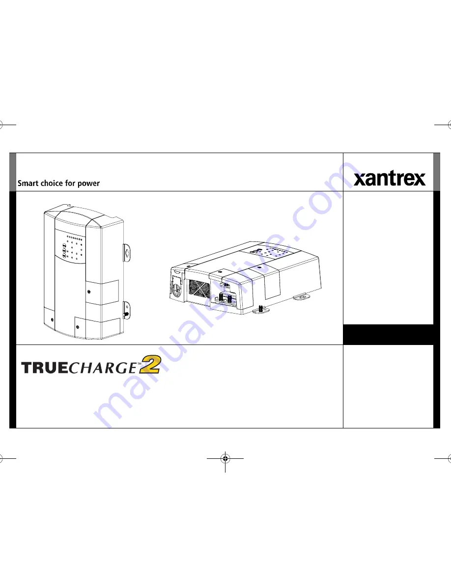
manualshive.com logo in svg
background image

TM

TM

Series Battery Charger

Owner’s Guide

TC2 204060 Series BattChg Owners Guide.book  Page i  Friday, July 8, 2011  11:44 AM

Содержание truecharge 2 series

Страница 1: ...TM TM Series Battery Charger Owner s Guide TC2 204060 Series BattChg Owners Guide book Page i Friday July 8 2011 11 44 AM...

Страница 2: ...TC2 204060 Series BattChg Owners Guide book Page ii Friday July 8 2011 11 44 AM...

Страница 3: ...Y TECHNICAL OR OTHER INFORMATION PROVIDED IN ITS MANUALS OR OTHER DOCUMENTATION B ASSUMES NO RESPONSIBILITY OR LIABILITY FOR LOSSES DAMAGES COSTS OR EXPENSES WHETHER SPECIAL DIRECT INDIRECT CONSEQUENT...

Страница 4: ...ed to install and configure any unit model of the Truecharge2 Series Battery Charger The installer should have knowledge and experience in installing electrical equipment knowledge of the applicable i...

Страница 5: ...e instructions can damage the unit and or damage other equipment IMPORTANT These notes describe things which are important for you to know however they are not as serious as a danger warning or cautio...

Страница 6: ...nnecting the DC Chassis Ground Earth on page 17 for instructions NOTE Turning off the battery charger using the on standby button on the optional remote panel will not reduce an electrical shock hazar...

Страница 7: ...le batteries because other battery types may explode and burst Do not work in the vicinity of lead acid batteries Batteries generate explosive gases during normal operation See note below Failure to f...

Страница 8: ...produce a short circuit current high enough to weld a ring or metal bracelet or the like to the battery terminal causing a severe burn 7 When removing a battery always remove the negative terminal fr...

Страница 9: ...States Coast Guard Electrical Regulations 33CFR183 Sub Part I EXPOSURE TO CHEMICALS AND GASES HAZARD Make sure the area around the battery is well ventilated Make sure the voltage of the batteries mat...

Страница 10: ...rference will not occur in a particular installation If this equipment does cause harmful interference to radio or television reception which can be determined by turning the equipment off and on the...

Страница 11: ...ng the Truecharge2 Battery Charger 34 Charging Batteries 35 Equalizing Flooded Batteries 37 Transitioning the Charger to ON Standby or Disabled 40 Accessing Charger Information 41 Using A Generator As...

Страница 12: ...TC2 204060 Series BattChg Owners Guide book Page ii Friday July 8 2011 11 44 AM...

Страница 13: ...programmable custom charge settings3 fully discharged battery charging4 ability to operate two Truecharge2 Battery Chargers in parallel mode with the use of the optional remote panel The Truecharge2 B...

Страница 14: ...C 13 F or below battery over temperature charging protection preventing battery charging at 70 C 158 F or higher and charging voltage compensation based on the temperature of the battery the optional...

Страница 15: ...d charging current 2 Mounting flanges are used to permanently install the product 3 DC wiring compartment cover protects the DC terminals as well as the communication and BTS ports Remove and replace...

Страница 16: ...he charger s chassis to ground Figure 2 Truecharge2 Battery Charger Rear Panel 2 1 5 7 9 6 3 4 40 A model TC4012 shown Other models may vary 8 Item Description 1 BTS port battery temperature sensor po...

Страница 17: ...panel buttons Figure 3 Onboard Control and Status Display Panel 2 4 5 6 1 3 Item Description 1 Charging Output LEDs The LEDs illuminate like a bar graph displaying the present total output charge cur...

Страница 18: ...he button for three seconds to select one of two settings An indicator LED corresponds to each setting Each setting optimizes the charging sequence differently in charging the batteries by stages Thre...

Страница 19: ...ensation Levels on page 32 RISK OF BATTERY DAMAGE Be sure the appropriate setting is selected before charging For varying conditions use the Warm setting Failure to follow these instructions can damag...

Страница 20: ...y charger must be installed by a qualified installer in accordance with all applicable local or national installation codes Examples of such codes are the US National Electrical Code NFPA 70 the Ameri...

Страница 21: ...ith your local electrical code requirements appropriately sized DC cables for each battery with suitable connectors at the battery end Use the information in DC Wiring on page 13 and your local electr...

Страница 22: ...in a tight fitting compartment the compartment must be ventilated with cut outs to prevent the charger from overheating Safea This battery charger except IEC modelsb is ignition protected equipment s...

Страница 23: ...ns that are suitable for each installation Is the installation environment one that will always be dry or will moisture or condensation sometimes enter the area ELECTRICAL SHOCK HAZARD In marine envir...

Страница 24: ...le from the charger may be an additional 6 10 above the nominal current rating of the charger Figure 6 Mounting Orientations Vertical Figure 7 Ventilation Clearance c d Vertical Wall Mount Rear panel...

Страница 25: ...ually DC rated circuit breakers fused disconnects or a separate fuse and disconnect for each circuit These devices must be rated for DC voltage and Table 1 DC Wiring Examples for 12 V chargersa a Valu...

Страница 26: ...must be protected by the appropriate size and type of input breaker based on the jurisdiction and application Some basic examples are given below The AC input wiring for the Truecharge2 Battery Charg...

Страница 27: ...ation codes If a fuse is used instead of a breaker a correctly rated disconnect switch is required ahead of the fuse so that power can be turned off allowing fuse replacement and safe maintenance of o...

Страница 28: ...the entry of dripping water and are not suitable for use in marine installations or other moist environments without the installation of additional drip protection They are only acceptable for use in...

Страница 29: ...ectly with the power conductors and both must be sized for the battery fuses that are used to protect the DC wiring Refer to your local electrical codes to verify the requirements in your jurisdiction...

Страница 30: ...ween the battery and the fuse or breaker For example for most situations ABYC standard E 11 requires no more than 7 inches 17 8 cm Be sure the breaker or fused disconnect is open 5 Route the wiring to...

Страница 31: ...ative DC terminal on the Truecharge2 Battery Charger Use a flat washer a lock washer and a nut five of each included in the installation kit to secure the connection 9 Tighten the nuts to 2 3 N m 20 l...

Страница 32: ...single negative cable connecting to the negative charger terminal 14 Secure cables in place using tie wraps or cable straps according to electrical codes 15 Slide the rubber boots to cover the DC ter...

Страница 33: ...d providing some slack 3 Route the AC supply wiring from the charger in its mounted position to the source 4 Unscrew the wiring compartment cover from the left rear of the Truecharge2 Battery Charger...

Страница 34: ...tion For example the ABYC Standards and Recommended Practices for Small Craft prohibit twist on connectors for AC connections on a boat For other types of installation refer to your applicable code b...

Страница 35: ...AC wiring access hole 12 Install the wiring compartment cover to fasten the strain relief and tighten the screw on top to secure the cover Do not over tighten 13 If applicable install the optional re...

Страница 36: ...er on test before reporting charging and battery status information NOTE Battery qualification may not be correctly performed if AC power is switched on first NOTE The onboard display LEDs will also i...

Страница 37: ...secondary charger between the two chargers Remember that only the primary charger or remote panel can be used to configure and operate the parallel system 4 Connect the primary charger s battery bank...

Страница 38: ...m either the remote panel or the primary charger s onboard display Follow the exact same procedures as a single charger when configuring the paralleled chargers When Equalizing Batteries Equalization...

Страница 39: ...or Negative chassis systems reconnect the positive cable first then the negative cable For Positive chassis systems reconnect the negative cable first then the positive cable Input Voltage Operating a...

Страница 40: ...ulk Absorption and Float or two stage charging Bulk and Absorption IMPORTANT The battery banks are not galvanically isolated from each other They share a common negative as shown in the diagram below...

Страница 41: ...ittle current The charger however is able to provide current to its full rating to power auxiliary DC loads on the battery The charger will restart the charging cycle in the Bulk stage if the lowest b...

Страница 42: ...stage sequence the charger will restart the charging cycle in the Bulk stage if the lowest battery voltage of the three banks drops below 12 5 V 12 Vdc chargers or 25 V 24 Vdc chargers for 15 minutes...

Страница 43: ...mple if Bank 1 and Bank 2 are both charged but Bank 1 has a load and Bank 2 does not then the charger may rarely charge Bank 2 Temperature Considerations Xantrex strongly recommends that you purchase...

Страница 44: ...re above 30 C 86 F See Table 7 Battery Temperature Compensation Levels on page 32 to see how output voltage is offset by varying the temperature selection RISK OF BATTERY DAMAGE Do not set a battery t...

Страница 45: ...ns and lights may vary in speed or intensity This is normal The Truecharge 2 Battery Charger will not harm any load connected to it as long as the load can withstand the following maximum voltages 16...

Страница 46: ...per charger mode The LEDs will indicate which of the two modes is being selected three stage default or two stage Configuring the Battery Bank Type NOTE By default the battery type is set to Flooded 1...

Страница 47: ...nitialization the indicator LEDs will display present status and settings At this point changes in Battery Type Battery Temperature and or Charger Mode can then be applied These settings are stored in...

Страница 48: ...he batteries charge Standby mode Or Rest mode If you selected the two stage charging mode the ready indicator LED shows the charger is now in rest mode and is continuously checking battery voltage Wit...

Страница 49: ...d lead acid or lead calcium batteries It does not enter equalization when the battery type is set to sealed lead acid batteries GEL or AGM since they will be damaged by this process Use the correct se...

Страница 50: ...initiate an equalize cycle Equalization will begin if all banks are in either float or rest mode RISK OF EQUIPMENT DAMAGE Turn off or disconnect all DC loads on the battery during equalization Do not...

Страница 51: ...o program another equalization cycle when the present cycle has not ended yet Carefully check the specific gravity of each cell and repeat the equalization cycle until they all meet the battery manufa...

Страница 52: ...ess ON STANDBY on the optional remote panel while batteries and AC power are both connected to the charger from ON The charger stops charging but continues to monitor the batteries There is only ONE w...

Страница 53: ...porting While Charging or Equalizing After configuring the charger and during charging the onboard display panel and the optional remote panel if installed will show the following information about th...

Страница 54: ...sappeared Under fault conditions the charging process will be stopped allowing either the charger or the battery or both to return within acceptable operating ranges See Specifications on page 54 for...

Страница 55: ...ry Temp fault 70 C Check the batteries Do not charge a battery that is rated other than 12 V nominal for all 12 volt chargers or 24 V nominal for all 24 volt chargers Check that the battery type and t...

Страница 56: ...he charger Disconnect voltage sensitive DC loads from DC supply to prevent damage If the DC bus voltage is still measuring high after AC power has been disconnected call a qualified and certified elec...

Страница 57: ...inals Disconnect AC and DC sources before replacing the fuse s on the charger See Replacing the DC Output Fuse on page 48 Internal fault Call Xantrex for support Flashing LED Solid LED Table 9 Interpr...

Страница 58: ...needs to run on full load capacity to supply charging current to the battery via the battery charger its output frequency and amplitude may become unstable This scenario can cause the battery charger...

Страница 59: ...gloves if you suspect it has come in contact with battery fluid salt water gasoline or oil or other corrosive material Do not operate if the charger contains moisture of any kind Periodically disconne...

Страница 60: ...use cover but do not over tighten 7 Fix the reverse polarity fault which caused the fuse to blow prior to reconnecting all AC and DC sources to the charger 8 Reconnect all AC and DC sources to the cha...

Страница 61: ...t with ratings as shown below Failure to follow these instructions can damage the unit and or damage other equipment Model Amperage Voltage TC2012 30 A green 32 Vdc TC4012 2 30 A green 32 Vdc TC6012 3...

Страница 62: ...re that power is available at charger AC input and it is within acceptable range Wiring must be inspected and replaced by a qualified installer Press the On Standby button on the remote panel to turn...

Страница 63: ...location If the optional remote panel is available you may reduce the output current using the Set Max Output button If battery is too cold allow batteries to warm up Possible Cause Solution Battery...

Страница 64: ...ge current so that battery does not recharge Battery has a damaged cell or has reached the end of its useful life The remote panel Max Output setting is too low for the battery capacity Use a higher c...

Страница 65: ...if the battery type is set to GEL or AGM These battery types cannot be equalized The charger will wait for all batteries to be in float stage of three stage charging or rest stage of two stage chargi...

Страница 66: ...ch North American trade size strain relief included AC input connections IEC models only IEC 60320 C14 male connector receptacle DC output connections Four M6 studs 3 positives and 1 common negative f...

Страница 67: ...C 77 F 28 8 0 2 Vdc 25 C 77 F Nominal battery voltage 12 volt units 24 volt units 12 Vdc 24 Vdc Normal operating output range 12 volt units 24 volt units 0 16 Vdc 0 32 Vdc Maximum DC output current t...

Страница 68: ...remote installed 35 mA dc DC Output Specifications Voltage regulation Uncompensated load voltage regulation 0 1Vdc drop from 0 Amps to rated current output at charger output terminals adds in series...

Страница 69: ...mperature below 25 C 13 F is sensed by the battery temperature sensor BTS Regulatory Approvals Safety North America NRTL approved to CSA E60335 2 29 UL1236 including the marine supplement and UL1564 A...

Страница 70: ...ng replacement products Xantrex reserves the right to use parts or products of original or improved design in the repair or replacement If Xantrex repairs or replaces a product its warranty continues...

Страница 71: ...al systems This warranty does not apply to and Xantrex will not be responsible for any defect in or damage to a the product if it has been misused neglected improperly installed physically damaged or...

Страница 72: ...RESULT OF MISUSE OR ABUSE OR THE INCORRECT INSTALLATION INTEGRATION OR OPERATION OF THE PRODUCT BY PERSONS NOT AUTHORIZED BY XANTREX CONSUMERS IN THE EUROPEAN UNION IF YOU ARE A CONSUMER RATHER THAN A...

Страница 73: ...t telephone number where you can be reached during work hours A brief description of the problem Ship the unit prepaid to the address provided by your Xantrex customer service representative If you ar...

Страница 74: ...3 804 2410 01 804 2420 01 804 2430 01 Purchased From ______________________ Purchase Date ______________________ Type of installation e g RV truck ______________________ Length of time unit has been i...

Страница 75: ...TC2 204060 Series BattChg Owners Guide book Page i Friday July 8 2011 11 44 AM...

Страница 76: ...Xantrex Technology USA Inc 1 800 670 0707 Tel 1 800 994 7828 Fax www xantrex com 975 0526 01 02 Printed in China TC2 204060 Series BattChg Owners Guide book Page ii Friday July 8 2011 11 44 AM...

Отзывы: