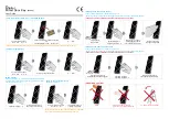
Thank you for purchasing the dual purpose RC400 Wired Digital Door Key / Digital Touch Pad.
1
COMPOSITION & SPECIFICATIONS
Wired Digital Door Key (RC400)
Mounting screws (4x16)
Mounting template
Connection wire
1EA
2EA
1EA
1EA
User’s Manual
1 copy
Power supply
Relay contact capacity
Operating temperature
Type
Power consumption
International Protection
DC 12~30V, AC 12~24V
DC30V / 1A
-20
℃
~50
℃
ISO14443A(Mifare) / 13.56MHz
300mA Under
IP54 (water proof)
Composition
Specification
D
igital
Wired Door Key
(RC400)
User Guide
2
DIMENSION
Unit : mm
3
OPERATION CHECK & CAUTION
5
CONTACT TIME
4
HOW TO USE
1. Be sure to connect DC12 ~ 30V / AC12 ~ 24V.
2. When it powers on, the LEDs will be displayed sequentially: once all LEDs have been displayed, “beep” sound is heard.
3. Since this system is capacitive touch type, it will not respond to a gloved hand.
①②③④ ⇒ ①②③④ ⇒ # ⇒ ① ⇒ # ⇒ Access card (Serial registration is possible) ⇒ # ⇒ * (end)
①②③④ ⇒ ①②③④ ⇒ # ⇒ ① ⇒ # ⇒ Card address(0001~0500) ⇒ Card ⇒ # ⇒ * (end)
Example) Serial registration : if the first address is [0100], next address is [0101] automatically increase.
①②③④ ⇒ ①②③④ ⇒ # ⇒ ③ ⇒ # ⇒ Card address (4digit or serial delete) ⇒ # ⇒ * (end)
4)
[Contact Time]
①②③④ ⇒ ①②③④ ⇒ # ⇒ ⑤ ⇒ # ⇒ 01~60 (01~60sec.) ⇒ # ⇒ * (end)
Example) Setup 2sec : 0+2, 20sec : 2+0 (Default value: 2sec)
5)
[All Card Delete]
①②③④ ⇒ ①②③④ ⇒ # ⇒ ⑥ ⇒ # (end)
6)
[All Password Delete]
①②③④ ⇒ ①②③④ ⇒ # ⇒ ⑦ ⇒ # (end)
7)
[Card or Password Delete]
Card : ①②③④ ⇒ ①②③④ ⇒ # ⇒ ⑧ ⇒ # ⇒ Access Card (Serial possible) ⇒ # ⇒ * (end)
Password : ①②③④ ⇒ ①②③④ ⇒ # ⇒ ⑧ ⇒ # ⇒ Password ⇒ # ⇒ * (end)
8)
[Toggle mode contact change]
①②③④ ⇒ ①②③④ ⇒ # ⇒ ②ⓞ ⇒ # ⇒ Set value (ⓞ~①) ⇒ # (end)
Set value - ⓞ : Normal , ① : Toggle mode (Default value : ⓞ)
9)
[Operation mode setting]
①②③④ ⇒ ①②③④ ⇒ # ⇒ ⑨ ⇒ # ⇒ Set value (ⓞ~①) ⇒ # ⇒ * (end)
Set value - ⓞ:NO, ①: NC (Default value : ⓞ)
10)
[Touch switch mode setting]
①②③④ ⇒ ①②③④ ⇒ # ⇒ ①① ⇒ # ⇒ Set value (ⓞ~①) ⇒ # (end)
Set value - ⓞ: touch switch mode is activated, ①: touch switch mode is deactivated (Default value : ⓞ )
For more detailed information, please refer to the back page “setting touch function to active”
11)
[Illumination brightness setting]
①②③④ ⇒ ①②③④ ⇒ # ⇒ ①② ⇒ # ⇒ Set value ⓞ~⑨) ⇒ # ⇒ * (end)
Set value -ⓞ: Illumination OFF, ⑨: The highest degree of brightness (Default value : ② )
In case brightness of the illumnination is set at off, press touch pad then the numbers will be appeared.
12)
[System number change]
①②③④ ⇒ ①②③④ ⇒ # ⇒ * ⇒ # ⇒ # ⇒ Number in use ⇒ # ⇒ New Number ⇒ # (end)
System number must be 4 digits (Default value : 1234)
13)
[System Initialization]
①②③④ ⇒ ①②③④ ⇒ * ⇒ # ⇒ Initializing ⇒ Exit after the LEDs blink. ⇒ (end)
①②③④ ⇒ ①②③④ ⇒ # ⇒ ② ⇒ # ⇒ Password(4digit) ⇒ # ⇒ * (end)
(Serial registration)
Power
(DC 12~30V, AC 12~24V)
Yellow
Yellow
White
White
Gray
Gray
External Input
Output Contact
2)
[Password Registration]
3)
[Card address Delete]
1)
[Card Registration]
6
EM LOCK WIRING
Output Contact
EM Lock
Adapter
Wiring
Wired Digital
Door Key
20
41
150
3
GENERAL INFORMATION
Unfasten the screw,
and use a flat blade (
⊖
)screwdriver
to disassemble it,
as shown in the figure below.
Water proof pad (Silicone rubber)
Between outside gaps
Screw for
disassembling
/assembling
Lower case
Connection
wire hole
Mounting screws
Disassembling the upper case
Water proof pad (Silicone rubber)
(When assembling the product,
the water proof pad should
not be twisted)
: Error
: Touch
: Ac on / Set
Upper case
Button
※
Use after removing the protective film
*


