Manual WIP1 GB
Woodward
DOK-TD-WIP1 Rev.F
26
5.7.4 Dimensioning example
For switching off a C.B. a tripping coil with a power of P
N
= 10 W and a rated current I
N
= 0.45 A is used.
As the rated current of the coil is a direct current, the setting value for the WIP1 for tripping with a single-
phase fault must be calculated as per eq. 1. This results in a setting value of 0.5 A.
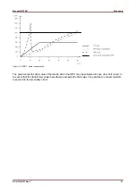
According to diagram 1 the impedance of the WIP1 at 0.45 A is approx. 8
Ω
.
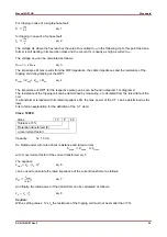
The resistance of the coil can be calculated as follows if it cannot be determined by measuring:
10
0.45
49.4Ω
For this example the cable impedance is assumed to be 0.5
Ω
.
According to eq. 4 the maximum impedance is as follows:
Z
max
= 57.9
Ω
.
Now the maximum voltage Umax can be calculated with eq. 3.
0.5 ∙ 57.9Ω
28.95
If a current transformer class 10P10 is used the resulting overcurrent factor is ü = 10. This permits calcula-
tion of the maximum power of transformer S
max
in accordance with eq. 5.
28.95 ∙ 10 ∙ 1
289.5
The rated impedance of the transformer is calculated in acc. with eq. 7.
289.5
10 ∙ 1
2.9Ω
And finally, eq. 8 can be used to calculate the rated power of the transformer.
2.9Ω ∙ 1
2.9
For this application a transformer with SN = 3 VA of Class 10P10 is used.
Equation 9 must now be used to check whether the WIP1 is possibly overloaded.
S
max
= 3VA -10
2
= 300VA < 1000 VA.
This means that this current transformer can be used.


