background image

C

B

A

3.4. INSTALLATIONS OF LOOSE PARTS 

H

G

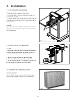
FIG. 4

FIG. 5

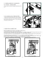
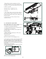
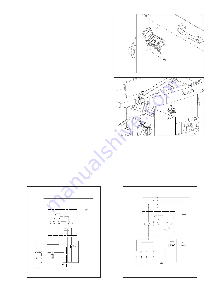
3.4.1 SWITCH - INSTALLATION

- Fit the switch (G, Fig.4) onto the bracket with two hex nuts (H, 
Fig.7)

3.4.2 Cutterblock guard - INSTALLATION

- Take off both of the hex socket screws (A, Fig.5). Install the 
cutterblock guard assembly (B, Fig.5) using two of hex socket 
screws. Make sure the square washer (C, Fig. 5) stay between 
the table and cutterblock guard.

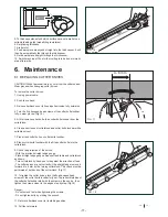
3.5 ELECTRICAL CONNECTION

Electrical installation should be carried out by competent, qualified personnel.

The mains connection should be made using the terminal box.

Ensure that the mains supply corresponds with that of the machine, use cables of a section suitable for the power of the motor. For a 

supply tension of 400 V the minimum section recommended is 2.5  mm, including the earth wire.

For a mains supply of 230 V or a power rating greater than 15 A it will be necessary to increase the section of the connecting cables .

Connect the phase wires to the terminals R- S - T (L1 - L2 - L3) and the earth wire to the earth terminal.     

On initial start-up check the direction of rotation, if it is incorrect then invert the two phase wires (for machines with 3 phase supply). 

Direction of rotation of machines with single-phase supply is pre-determined during production . 

On completion of the installation check that the terminal box is closed correctly and that the plug points are locked.

PE

N

34

44

b

33

43

a

L

OL

ON

OFF

Motor

Safty

switch

Y ell ow G re en

Bl ue

Br ow n

B la ck

Br ow n

B lu e

23

33

43

a

b

44

34

24

OL

ON

OFF

L1

PE

L3

L2

Motor

Safty

Switch

Y e ll o w G r e en

B l ue

B r ow n

Gr a y

B ro w n

Bl u e

B l a ck

PT310 Single phase

PT310 Three phase

-7-

Содержание PT310X

Страница 1: ...NG THIS PRODUCT 3AVE THIS MANUAL FOR FUTURE REFERENCE 4 3 49 5 3 LWAYS FOLLOW THE INSTRUCTIONS PROVIDED WITH THE MANUAL LWAYS WEAR SAFETY GLASSES WHEN USING WOODWORKING EQUIPMENT LWAYS DISCONNECT THE POWER BEFORE ADJUSTING ANY EQUIPMENT AILURE TO OBSERVE PROPER SAFETY PROCEDURES AND GUIDELINES CAN RESULT IN SERIOUS INJURY 7 2 O NOT ALLOW FAMILIARITY GAINED FROM FREQUENT USE OF YOUR MACHINE AND ACC...

Страница 2: ...ng and unloading 3 2 Position of the machine 3 3 Identifying shipping boxes 3 4 Installations of loose parts 3 4 1 Fence installation 3 4 2 Switch installation 3 5 Electrical connection 3 6 Dust chute installation 4 INSTALLATION AND ADJUSTMENT 4 1 Thicknesser table height adjustment 4 2 Infeed table height adjustment 4 3 Jointer fence adjustment 5 OPERATING PROCEDURES 5 1 ON OFF switch 5 2 Surface...

Страница 3: ...n the best results 2 Machine Description 2 1 MACHINE IDENTIFICATION There is a metallic identification plate fixed to the machine containing the manufacturer s data year of construction serial number 2 2 GETTING TO KNOW YOUR MACHINE 1 Jointer fence 2 Infeed table 3 Height setting of infeed table 4 Cutterblock 5 On off switch 6 Locking level 7 Outfeed table 8 Cutterblock guard 9 Height setting of t...

Страница 4: ... necessarily safe working levels Whilst there is a correlation between the emission and exposure levels this cannot be used reliably to determine whether or not further precautions are required Factors that influence the actual level of exposure of the workforce include the characteristics of the work room and the other sources of noise etc i e the number of machines and other adjacent processes A...

Страница 5: ... once Risk of injury by kickback if a blunt knife gets caught in the workpiece s surface Risk of injury by an unstable stand of the planer thicknesser when working long stock use suitable supports on both sides of the machine Avoid adverse body positions Ensure firm footing and keep your balance at all times Risk of injury by foreign objects in the machine prior to any starting of the machine ensu...

Страница 6: ...the machine weight 3 2 POSITION OF THE MACHINE CAUTION It is prohibited to install the machine in explosive environments Ensure that the floor area around the machine is level well maintained and free from loose material e g chips 1 Remove four mounting bolts from the machine base 2 Lift machine off the pallet and set down on the floor 3 Fix the machine to the floor Fix the machine feet and fix on...

Страница 7: ...on of 400 V the minimum section recommended is 2 5 mm including the earth wire For a mains supply of 230 V or a power rating greater than 15 A it will be necessary to increase the section of the connecting cables Connect the phase wires to the terminals R S T L1 L2 L3 and the earth wire to the earth terminal On initial start up check the direction of rotation if it is incorrect then invert the two...

Страница 8: ...h a handwheel B Fig 7 One full turn of the crank changes the height of the thicknesser bed C Fig 7 by 4 mm Clockwise turning raises the thicknesser bed Counter clockwise turning lowers the thicknesser bed The set planing thickness is indicated on the scale D Fig 7 4 2 INFEED TABLE HEIGHT ADJUSTMENT With the height setting for the infeed table E Fig 8 the depth of cut is set when the machine is use...

Страница 9: ... Workpiece dimensions Length use a push stick to feed workpieces shorter than 250 mm for workpieces over 1500 mm use a second person for support Width max 310 mm Thickness min 5 mm Note The max depth of cut for a single pass is 3 mm 1 Assume proper operating position position yourself to one side of the infeed table 2 Set jointer fence as required 3 Set planing thickness 4 Place workpiece against ...

Страница 10: ...rough the thicknesser The surface already planed flat rests on the thicknesser bed The workpiece is cut on the upper side The feed direction of the workpiece is exactly opposite than with surface planing Workpiece dimensions Length min 200 mm for workpieces over 1500 mm use a second person for support Width max 305 mm Thickness min 6 mm max 200 mm Note The max depth of cut for a single pass is 3 m...

Страница 11: ...an all surfaces of cutterblock and cutter knife lockbar with a suitable solvent 7 Place fresh cutter knife on cutter knife lockbar 8 Place cutter knife lockbar with the fitted cutter knife into the cutterblock 9 Check the projection of the knives With the provided straight edge gauge Place straight edge gauge across outfeed table and cutterblock as shown Turn cutterblock by hand one turn against t...

Страница 12: ...The drive belt should not give more than 10 mm in the centre Tensioning the drive belt 5 From outside the machine loosen the four nuts D Fig 20 using stick E Fig 20 to increase the motor the cutterblock drive belt will be slackened CAUSTION When increase the motor by stick don t damaged the motor wiring box 6 To tension the cutterblock drive belt push the motor downward When belt tension is correc...

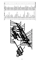
Страница 13: ...E 13A P226E 03A 1 12 Pan screw M4X16GB823Z 4 13 Nut M8GB6172Z 4 14 Ball head bolt JL45030016 4 15 Scale JL45040019 1 16 Square neck bolt M12X65GB801Z 1 17 Hex Screw M6X25GB70D2B 2 18 Plate JL45090003 1 19 Rod JL45090005 1 20 Nut M6GB41Z 2 21 Locknut M4GB889Z 2 22 Switch plate JL45090004 1 23 Switch QKS7 1 24 Pan screw M4X30GB818Z 2 25 Locknut M6GB889Z 2 26 Plat washer WSH6GB97D1Z 6 27 Hex locknut ...

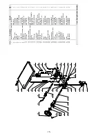
Страница 14: ...8 Non return block JL45020010A 18 19 Right cutterhead bracket JL45020001 1 20 Retainer ring CLP52GB893D1B 2 21 Washer JL45051005 2 22 Spring JL45020004 4 23 Screw JL45020003 4 24 Hexagon bolt M10X25GB5783B 4 25 Rod JL45020009 1 26 Bush JL45020011 27 27 Rod JL45020008 1 28 Infeed roller JL45020005 1 29 Big chain wheel JL45050003 2 30 Hexagonal self locking nut M10GB889Z 2 31 Pin PIN5X18GB879B 1 32 ...

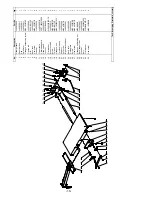
Страница 15: ...ing BRG6202 2Z P5GB276 1 15 Nut M6GB6170Z 4 16 Circlip ring CLP35GB893D1B 1 17 Locking lever JL45040008 1 18 Handwheel SGSL D160 d12A1 1 19 Adjustable handle KTSB 1 B M8X63X20 1 20 Thin nut M8GB6172Z 1 21 Flat washer WSH6GB97D1Z 4 22 Rings JL45040014 2 23 Screw M6X25GB70D2B 4 24 Rod JL45040012 1 25 Thicknesser table JL45040001A 1 26 Indicator JL45040020 1 27 Spring washer WSH10GB93Z 2 28 Hexagonal...

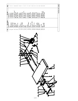
Страница 16: ...Cutterhead guard FDPT1202070000 1 13 Hand shank JL45030012 1 14 Locknut M12GB889B 2 15 Flat washer WSH12GB97D1Z 2 16 Eccentric shaft JL45030015 2 17 Screw M8X60GB70B 2 18 Thin nut M8GB6172Z 2 19 Hexagon bolt M8X16GB5781Z 1 20 Torsional spring JL45030009 1 21 Support JL45030005 1 22 Set screw M6X8GB77B 1 23 Big deflection wheel JL45090001 1 24 Back rack JL45030004 1 25 Guide plate JL45060028 1 26 S...

Страница 17: ...Rod JL45030011 1 11 Locknut M12GB889B 2 12 Rising rack JL45030006 1 13 Planer table JL45030001B 1 14 Screw M8X16GB5781Z 1 15 Nut M8GB6170Z 1 16 Block JL45030018 1 17 Spring JL45030009 1 18 Support base JL45030005 1 19 Nut M8GB6172Z 4 20 Hex screw M8X12GB70Z 1 21 Eccentric shaft JL45030015 2 22 Screw M8X60GB70B 2 23 Front Rack JL45030003 1 24 Screw M8X10GB70B 2 25 Hex screw M8X40GB77B 1 26 Guide pl...

Страница 18: ...lf locking nut M10GB889Z 1 10 Belt wheel JL45051101 1 11 Bearing BRG6000 2ZGB276 2 12 Circlip ring CLP10GB894D1B 2 13 V belt JL45050007 1 14 Chain wheel spindle JL45051004 1 15 Washer WSH10GB97D1Z 1 16 Panel assembly JL45051300 1 17 Handle sleeve JL45050013 1 18 Big gearwheel JL45051001 1 19 Belt wheel spindle JL45051301 1 20 Minor sprocket bush JL45051003 1 21 Washer JL45051005 1 22 Circlip ring ...

Страница 19: ...B70D3Z 2 12 Right support arm JL45060020 1 13 Nut M8GB6172Z 2 14 Lock tube JL45060024 2 15 Lock rod JL45060023 1 16 Lock handle JL45060027 1 17 Hex Screw M6X16GB70Z 2 18 Angle label JL45060007B 1 19 Hex Screw M8X20GB70Z 2 20 Left support arm JL45060021 1 21 Support plate JL45063000A 1 22 Big washer WSH6GB96Z 6 23 Indicator JL45060026 1 24 Washer WSH4GB97D1Z 2 25 Hex Screw M4X5GB70Z 2 26 Spring was...

Отзывы: