background image

Troubleshooting Guide

5-3

RANGES &

& R

RANGETOPS

PROBLEM

POSSIBLE CAUSE

TEST / ACTION

A. CONSTANT SPARKING AT

SURFACE BURNERS

B. INTERMITTENT SPARKING

AT SURFACE BURNERS

C.  POOR IGNITION AT SUR-

FACE BURNERS

Burner base not properly positioned on

burner body

Electrode wired in wrong position at module

Ground wire disconnected at outlet in wall

Reverse Polarity at outlet power supply or

power cord

Defective micro switch at burner valve

Arc at cut or splice in electrode wire

Cable ties on wire too tight

Defective spark module

Arcing at module to bracket or chassis

Dirty electrode

Cracked or damaged electrode

Electrode wired in wrong position at module

Broken micro switch at burner valve

Electrode wires touching each other/metal

Arc at cut or splice in electrode wire

Defective spark module

Bad connection at the molex connector on

the spark module

Arcing at module to bracket or chassis

Outer burner ring not correctly placed on

the burner base

Burner base not properly positioned on

burner body

Burner base may be binding on pressed

steel top and lifting

Partially plugged holes or slots in the burn-

er head

Improper Gas orifice

Gas pressure

Rotate to correct position and advise owner

Check routing from wiring diagram for model

Have electrician repair

May have to call an electrician.  May have to

properly wire the power cord to the unit.

Replace micro switch

Replace electrode wire

Cut tie and replace so wire is loose

Replace spark module

Check for break in insulation or missing fish

paper shield

Clean with wire brush

Replace electrode

Check routing from wiring diagram for model

Replace micro-switch

Separate and cover with sleeving

Replace electrode wire

Replace spark module

Determine by continuity check

Check for break in insulation

Rotate to correct position and advise owner

Rotate to correct position and advise owner

Check to see that there is an even concentric

clearance between the burner base and the
pressed steel top.  The burner support may
have to be repositioned

Clear as necessary

Check orifice stamp number

Check for type gas and check gas pressure with

a manometer

Содержание RT362F

Страница 1: ...Technical Service Manual WOLF APPLIANCE COMPANY L L C 2004 ALL RIGHTS RESERVED JOB AID 803331 Revision E Aug 2004 Ranges 30 Inch 36 Inch 48 Inch 60 Inch Rangetops 36 Inch 48 Inch ...

Страница 2: ......

Страница 3: ...General Information RANGES R RANGETOPS 1 1 SECTION 1 GENERAL INFORMATION ...

Страница 4: ... compiled to provide the most recent techni cal service information about the Wolf Appliance Company LLC Ranges and Rangetops This information will enable the service technician to troubleshoot and diagnose malfunctions perform necessary repairs and return a Wolf Range and or Rangetop to proper operational condition The service technician should read the complete instructions contained in this Tra...

Страница 5: ... Information RANGES R RANGETOPS 1 3 TABLE OF CONTENTS Page Page Section 1 General Information Introduction 1 2 Important Safety Information 1 2 Technical Assistance 1 2 Table of Contents 1 3 Warranty Information 1 5 Model Features 1 6 Model Key 1 7 Top Configurations 30 36 48 Ranges 1 8 Top Configurations 60 Range 1 9 Top Configurations Rangetops 1 10 Section 2 Theory of Operation Types of Fuel Ga...

Страница 6: ... 7 15 Model R606F 7 16 Model R606CG 7 17 Model R604CF 7 18 Model R604GF 7 19 RANGETOPS Model RT366 7 20 Model RT364C 7 21 Model RT364G 7 22 Model RT362F 7 23 Model RT488 7 24 Model RT486C 7 25 Model RT486G 7 26 Model RT484CG 7 27 Model RT484DC 7 28 Model RT484DG 7 29 Model RT484F 7 30 Model RT484F 7 31 Page ...

Страница 7: ...RTICAL DISTANCE BETWEEN TH 3 MUM DEPTH FOR OVERHEAD CABINETS IS 1 AND SIDE OF THE APPLIANCE 0 MAXI THE COOKING SURFACE AND THE BACK ADJACENT COMBUSTIBLE MATERIALS BELOW L MINIMUM CLEARANCE BETWEEN 12 FROM SIDE WALLS 0 FROM REAR WAL E TENDING 18 ABOVE THE COOKING SURFAC ADJACENT COMBUSTIBLE CONSTRUCTION EX DES AND BACK OF APPLIANCE TO MINIMUM HORIZONTAL CLEARANCE FROM SI 800117 A MAN PRESS INPUT RA...

Страница 8: ...s Door windows and interior lights in ovens Porcelain oven interior 3 76 mm adjustable stainless steel legs in front and adjustable rear casters Full side panels and skirt High altitude conversion kit available Optional risers 5 127 mm 10 254 mm and 20 508 mm with shelf Two and five year residential warranty CSA certified for US and Canada RANGETOP FEATURES Natural or LP gas models Classic stainle...

Страница 9: ... 48 48 inch wide unit 60 60 onch wide unit Surface Burners 2 2 open burners 4 4 open burners 6 6 open burners 8 8 open burners Model Features C 2 open burners G 4 open burners F 6 open burners DG Double Griddle 22 DC Double Charbroiler 22 Fuel LP Propane Gas Propane Gas will be indicated by LP at the end of the model number Example R606CG LP LP NOTE If model number doesn t have LP at the end unit ...

Страница 10: ...en Burners w 11 Charbroiler R364G AS36Ki 6 4 Open Burners w 11 Griddle R488 PS488K 8 Open Burners R486C PS486BK 6 Open Burners w 11 Charbroiler R486G PS486GK 6 Open Burners w 11 Griddle R484CG PS48GBK 4 Open Burners w 11 Charbroiler 11 Griddle R484DC PS484BK 4 Open Burners w 22 Charbroiler R484DG PS484GK 4 Open Burners w 22 Griddle R484F PS484FK 4 Open Burners w 22 French Top R482CF PS48FBK NOTE L...

Страница 11: ...rbroiler R606DC S60BKK R606DG S60GKK 6 Open Burners w 22 Griddle R606F S60FKK 6 Open Burners w 22 French Top R606CG S60GBKK 6 Open Burners w 11 Charbroiler 11 Griddle R604CF S60FBKK 4 Open Burners w 11 Charbroiler 22 French Top R604GF S60FGKK 4 Open Burners w 11 Griddle 22 French Top NOTE LP Following the New Model Number signifies Propane Gas ...

Страница 12: ...4G 4 Open Burners w 11 Griddle RT362F SB362F 2 Open Burners w 22 French Top RT488 SB488 8 Open Burners RT486C SB486B 6 Open Burners w 11 Charbroiler RT486G SB486G 6 Open Burners w 11 Griddle RT484CG SB48GB 4 Open Burners w 11 Charbroiler 11 Griddle RT484DC SB484B 4 Open Burners w 22 Charbroiler RT484DG SB484G 4 Open Burners w 22 Griddle RT484F SB484F 4 Open Burners w 22 French Top RT482CF SB48FB N...

Страница 13: ...Theory of Operation 2 1 RANGES R RANGETOPS SECTION 2 THEORY OF OPERATION ...

Страница 14: ...he variance is due to the various other substances found in natural gases The more ethane propane or butane in the gas raises the heating value Propane or LP gas has a heating value of about 2500 BTU per cubic foot and butane about 3200 BTU per cubic foot Specific Gravity of Gas The specific gravity of a gas is the weight of one cubic foot or the gas compared to one cubic foot of dry air When stat...

Страница 15: ... assure complete burning of the gas The total air primary secondary and excess are expressed as percentages of the amount needed About ten cubic feet of air is required to com pletely burn one cubic foot of gas For this reason an appliance should not be operated in an air tight home Limits of Flammability Not all air to gas mixtures will burn Mixtures with 0 4 natural gas in air are too lean to bu...

Страница 16: ...ir injection Mixing Tube Throat Serves to carry the gas air mixture from the venturi tube to the burner body Burner Body The accumulation chamber below the burner base which allows the gas and air to mix together fully Burner Base Cross Over Ring The component below the burner ring which carries the gas air mixture to the burner ring Burner Ring Burner Head The component containing the burner port...

Страница 17: ...visible and glows only because of the high temperature of the final combustion Infrared Burners Wolf gas ranges also use two types of infrared burners The under fired application for the char broiler and the griddle uses a porous refractory ceramic tile burner See Figure 2 2 An over fired screen type burner is used in the oven broiler With these two types of burners a substantial amount of energy ...

Страница 18: ...to allow a spe cific quantity of gas to pass through This is how the size of the flame is adjusted See Figure 2 4 After the valve the gas is piped to a gas orifice which is an opening of very small diameter The gas is pushed through the small diameter of the gas orifice so when it exits it is under high velocity This high velocity stream of gas causes a drop in pressure around itself The low press...

Страница 19: ...ure as it leaves the burner ports which causes ignition See Figure 2 7 With the proper gas and air mixture a flame of natural gas should be blue with a deep blue inner cone and have no trace of yellow flame See Figure 2 8 With liquid propane gas some orange tipping is acceptable In both cases the flame should be odorless and completely free of dangerous gases GAS GAS AIR MIX Venturi Tube Figure 2 ...

Страница 20: ...RANGES R RANGETOPS Theory of Operation 2 8 ...

Страница 21: ...Installation Information RANGES R RANGETOPS 3 1 SECTION 3 INSTALLATION INFORMATION ...

Страница 22: ...tomer Service Department Gas Pressure NOTE All Wolf gas appliances are manufactured to work with natural gas but Wolf gas appliances can be converted to work with LP gas Liquid Propane gas Natural Gas Manifold Pressure Standard natural gas orifices on the appliance are set for 5 WC Water Column Pressure Liquid Propane Manifold Pressure The standard propane gas orifices in a conversion kit will be ...

Страница 23: ...ges can be leveled at the front by adjusting the 3 76 mm adjustable front legs See Figure 3 3 In order to level the rear of the unit use the caster wrench p n 803239 to rotate the 2 5 16 59 mm nut clockwise to raise or counterclockwise to lower the unit See Figure 3 4 Use shims to level a wolf rangetop UP Figure 3 3 Unit Leveling Front Leveling Leg Wall Floor Side Panel Anti Tip Bracket Rear Chann...

Страница 24: ...LA INSTALLATION NO SIDE WALL ABOVE COOKING SURFACE 12 305 MINIMUM CLEARANCE TO COMBUSTIBLE MATERIALS Ð 0 0 TO NON COMBUSTIBLE MATERIALS ISLAND INSTALLATION LOCATION OF ELECTRICAL C LOCATION OF GAS SUPPLY A OVERALL WIDTH 351 2 902 36 914 36 914 37 940 COOKING SURFACE ISLAND OR PENINSULA INSTALLATION 413 4 1060 5 127 RISER 10 254 RISER 20 508 RISER 463 4 1187 563 4 1441 21 2 64 271 4 692 283 8 721 O...

Страница 25: ...OVE COOKING SURFACE PENINSULA INSTALLATION NO SIDE WALL ABOVE COOKING SURFACE 12 305 MINIMUM CLEARANCE TO COMBUSTIBLE MATERIALS Ð 0 0 TO NON COMBUSTIBLE MATERIALS ISLAND INSTALLATION 91 2 241 14 356 C LOCATE ELECTRICAL AND GAS SUPPLY WITHIN SHADED AREA THROUGH BOTTOM OF PLATFORM TOP VIEW OF PLATFORM E G C 3 76 BACK WALL 1 2 13 24 610 23 4 70 3 4 19 PLATFORM 3 4 19 PLATFORM A OVERALL WIDTH 20 508 1...

Страница 26: ...RANGES R RANGETOPS Installation Information 3 6 ...

Страница 27: ...Component Access Removal 4 1 RANGES R RANGETOPS SECTION 4 COMPONENT ACCESS AND REMOVAL ...

Страница 28: ...R TO THE UNIT MUST BE DISCONNECTED WHENEVER ACCESSING AND OR REMOVING COMPONENTS POWERED BY ELECTRICITY OR COMPONENTS NEAR OTHER ELECTRICAL COMPONENTS IF IT IS NECESSARY TO REMOVE A UNIT FROM ITS INSTALLATION REMEMBER THAT THE UNIT COULD TIP FORWARD WHEN PULLED FORWARD BEYOND THE ANTI TIP COMPONENTS RESULTING IN SERIOUS INJURY OR DEATH PULLING A UNIT FROM ITS INSTALLATION SHOULD ONLY BE PERFORMED ...

Страница 29: ...can be removed Once the back panel is removed disconnect the appro priate electrode wire from the spark module and clip any cable ties around the wire being removed With wrenches disconnect the inner burner gas supply line from the burner body See Figure 3 3 With one wrench on the outer burner orifice holder use another wrench to disconnect the flexible gas line which supplies the outer burner See...

Страница 30: ... its installation and the back panel must be removed Once the back panel is removed disconnect the appropriate electrode wire from the spark module Then using an 10mm allen wrench remove the inner burner base Access the bottom of the burner body and locate the E ring at the base of the electrode Remove the E clip using a small flat blade screwdriver Then pull the electrode and its wire out form th...

Страница 31: ...red Charbroiler Burner Box Removal After removing the components listed above extract the screw securing the sparker bracket Then extract the screw from the rear of the IR burner box Extract the screws from the heat shield baffle and lift it out Disconnect the gas line from the brass orifice elbow and lift the burner box out See Figure 3 10 Infrared Charbroiler Sparker Removal The infrared Charbro...

Страница 32: ...late Then lift the plate straight up until the drain spout clears the unit frame Now tilt the griddle plate forward until it is verti cal and lift straight up to disengage the thermostat bulb from the channel See Figure 3 11 Infrared Griddle Orifice Removal The orifice is located in the brass orifice elbow which is threaded into the orifice holder at the front of the burner box NOTE It is possible...

Страница 33: ...ads from the thermostat Pull the control knob from the shaft of the thermostat and extract the thermostat mounting screws Pull the thermostat bulb from the channel at the bottom of the griddle plate and lift the thermostat from the unit See Figure 3 15 Infrared Griddle Sparker Removal The infrared griddle sparker is attached to a bracket with a screw and then mounted 1 32 above the surface of the ...

Страница 34: ...iance See Figure 3 18 French Top Electrode Electrode Wire Removal Electrode Begin removing the electrode by discon necting the electrode wire terminal from the electrode Remove the retaining clip from the bottom of the elec trode and pull the electrode up out of its mounting hole See Figure 3 18 Electrode Wire The French Top electrode wire has a terminal at one end that fits onto the base of the e...

Страница 35: ...of the switch or light while pushing it towards the front of the panel See Figure 3 21 Thermostat and Thermostat Bezel Removal After tilting the top of the control panel forward discon nect the electrical leads from the thermostat Extract the thermostat mounting screws which pass through the bezel into the thermostat bracket Now push the thermostat back out of the control panel See Figure 3 21 NOT...

Страница 36: ... the bolts from the valve body and mounting bracket Now pull or twist the valve off of the manifold pipe See Figure 3 24 Charbroiler or French Top Valve Removal To remove a Charbroiler or French Top valve first dis connect the gas lines from the valve first Then remove the ninety degree elbow from the rear of the valve NOTE Depending on the location of other components on the manifold it may be ne...

Страница 37: ...valve is attached to the bot tom frame brace with a screw To remove the oven burner bi metal valve first discon nect the electrical leads and the gas lines Then extract the mounting screw and lift the bi metal valve from the appliance See Figure 3 28 Oven Burner Orifice Removal The oven orifice is bell shaped with a hex shaped end One end of the oven orifice elbow is inserted through a hole in the...

Страница 38: ...e light socket the unit must be pulled from its installation and the back panel removed Then disconnect the electrical leads from the socket terminals With a small flat blade screwdriver gently expand the metal tabs on each side of the ceramic socket and pull the socket out of the lamp base See Figure 3 29 Oven Convection Fan Removal The convection fan assembly is held to the back wall with screws...

Страница 39: ...e brace Cut any cable ties that may be around the glow coil wires Extract the screw at the back of the oven burner tube Lift the rear of the burner tube slightly while pulling it towards the rear of the unit Now extract the glow coil igniter mounting screws pull the igniter away from the burner tube and lift the burner tube up and out of the oven See Figure 3 33 Oven Glow Coil Igniter Removal Two ...

Страница 40: ...d pull the igniter wires down and out of the hole in the oven side wall See Figure 3 34 Oven Infrared Broiler Burner Removal The broiler burner box sits in a pocket at the top of the oven The burner mixing tube runs from the burner box to the back side of the appliance The orifice holder bracket is welded to the back end of the mixing tube The broiler burner is held in place by four brackets place...

Страница 41: ...ot remove the two outer hinge pin mounting screws See Figure 3 35 After loosening the screws disengage the hinge pin from the trunion bolt using a nut driver to slide the two outer hinge pin mounting screws towards the center of the door Now lift the door assembly off of the unit See Figure 3 35 Disassembling Oven Door If it is necessary to access or remove any of the com ponents that make up the ...

Страница 42: ...iler orifice elbow which is threaded into the broiler ori fice holder on the back end of the broiler mixing tube To remove the the orifice first remove the flue which covers the orifice holder Disconnect the gas line from the brass elbow and unscrew the elbow from the orifice holder Now use wrenches to remove the orifice from the hold er See Figure 3 37 Spark Module Removal NOTE It is recommended ...

Страница 43: ...Troubleshooting Guide 5 1 RANGES R RANGETOPS SECTION 5 TROUBLESHOOTING GUIDE ...

Страница 44: ...ng guide table of contents shows how the troubleshooting guide is laid out The troubleshooting guide is organized into component areas with the most common problems listed first On the table of contents below identify the description of the problem that the unit is experiencing To the left of the problem description is a letter Locate that letter in the left column of the Troubleshooting Guide The...

Страница 45: ... Burner base not properly positioned on burner body Burner base may be binding on pressed steel top and lifting Partially plugged holes or slots in the burn er head Improper Gas orifice Gas pressure Rotate to correct position and advise owner Check routing from wiring diagram for model Have electrician repair May have to call an electrician May have to properly wire the power cord to the unit Repl...

Страница 46: ...nd wire disconnected at outlet or on power cord to junction box Reverse polarity at outlet power supply or power cord Defective micro switch at burner valve Cable ties on wire too tight Defective spark module Arcing at spark module to bracket or unit chassis Replace micro switch Replace repair wiring Replace spark module Check outlet and circuit breaker Check gas pressure with a manometer Adjust a...

Страница 47: ...ark module No power No gas Short to spark module bracket unit chassis Unit not level Needs blank off plate Clean food debris from sparker Replace sparker Check routing from wiring diagram for model Replace micro switch Separate and cover with sleeving Replace sparker Determine by continuity check Repair replace molex connector Replace spark module Replace sparker The strap and sparker should be cl...

Страница 48: ... enough to tile surface Partially plugged holes in the burner tile Wrong orifice size Gas pressure Blockages in mixer tube or orifice Bent orifice bracket holder Check routing from wiring diagram for model May have to call an electrician May have to call an electrician May have to properly wire the power cord Replace solenoid assembly Replace thermostat Replace sparker Cut tie and replace the wire...

Страница 49: ...ectrode wired in wrong position at module Arc at cut or splice in electrode wire Electrode wires touching each other or metal Bad connection at molex connector on spark module Broken micro switch at burner valve Defective spark module Replace sparker Replace solenoid or valve Check all wires per wiring diagram Replace spark module Replace thermostat Visually inspect the spark module or bracket for...

Страница 50: ...r thermostat out of calibration Locate per owner s manual and advise owner Clear as necessary Replace electrode or wiring Check orifice number stamped on orifice Check gas pressure with a manometer Check per wiring diagram Replace electrode Replace spark module Check outlet and circuit breaker Check gas pressure with a manometer Level unit from front to rear and side to side Place as shown in owne...

Страница 51: ... tube Reverse the bracket so the flange faces toward the back of the unit Replace if not drawing 3 3 to 3 6 amps See procedure in technical section Straighten so that gas jet is aimed straight down venturi tube replace if necessary Replace if not drawing 3 03 to 3 3 VAC See procedure in technical section Straighten the capillary tube or replace the ther mostat Replace thermostat Clear as necessary...

Страница 52: ...y flames licking out from large pots at rear burners Straighten and position Replace if not drawing 3 3 to 3 6 amps Replace if not drawing 3 03 to 3 3 VAC Straighten so that gas jet is aimed straight down venturi tube replace if necessary Clear as necessary Straighten so that gas jet is aimed straight down venturi tube replace if necessary Gas is burning between screens or in box Broiler needs to ...

Страница 53: ...Technical Data 6 1 RANGES R RANGETOPS SECTION 6 TECHNICAL DATA ...

Страница 54: ...e 46 800047 Burner Oven Broil 18 000 Orifice 48 800259 French Top 15 000 Orifice 170 800060 Burner Oven Tube 30 000 Large Oven Orifice 36 800071 Burner Oven Tube 18 000 Small Oven Orifice 48 800073 ORIFICE CHART Natural Gas 5 WC Description BTU Stamp No Part No Valve Burner 16 000 Orifice Inner Bypass 25 800055 Orifice Outer Bypass 54 800054 Burner Body Assy 16 000 Orifice Inner 7 800052 Orifice O...

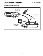
Страница 55: ...Technical Data 6 3 RANGES R RANGETOPS L1 Neutral 110 120 VAC Input 96 VAC Minimum 3 03 to 3 3 VAC Valve Opens When Glow Coil draws 3 3 to 3 6 amps Valve Operates CHECKING OVEN IGNITION SYSTEM ...

Страница 56: ...RANGES R RANGETOPS Technical Data 6 4 ...

Страница 57: ...R RA AN NG GE ES S R RA AN NG GE ET TO OP PS S Wiring Diagrams 7 1 WIRING DIAGRAMS SECTIO N 7 ...

Страница 58: ...3 5 6 12 10 9 11 8 10 8 9 11 12 RED 40 BROWN 39 BLACK 35 BLUE 28 BROWN 27 WHITE 24 BLACK 21 YELLOW 31 BLACK 23 BLACK 22 WHITE 24 WHITE 26 THERMOSTAT BLACK 41 BROWN 13 FAN SWITCH PURPLE 34 BLACK 21 WHITE 25 RED 32 OVEN SAFETY WHITE 19 PURPLE 10 RED 8 PURPLE 11 1 3 5 2 6 4 8 7 SAFETY BROILER 19 09 2028 PLUG 19 09 1029 RCPT BROILER IGNITOR 1 2 1 2 C BA BR 1 1 19 09 2019 PLUG 19 09 1019 RCPT WHITE 29 ...

Страница 59: ...ETY 1 7 8 5 6 3 4 2 2 2 OVEN SAFETY OVEN IGNITOR RED 8 PURPLE 11 FRONT PANEL 1 1 P R PLUG 3 CONDUCTOR POWER CORD WHITE BLACK GREEN GROUND J BOX OVEN LIGHT N MOTOR 115V 60HZ DOOR SWITCH BROWN 35 RED 45 MOLEX G 1 MOLEX G 2 12 12 11 11 8 8 9 9 7 7 6 6 10 10 5 5 4 4 3 3 2 2 1 1 19 09 1129 RCPT 19 09 2128 PLUG BLACK 50 BROWN 55 RED 56 PURPLE 47 LEFT REAR LEFT FRONT S6 S5 S4 S3 S2 S1 7 6 POINT SPARK MOD...

Страница 60: ...ITE 3 WHITE 2 BLACK 1 BLACK 15 BROILER SAFETY 1 7 8 5 6 3 4 2 2 2 OVEN SAFETY OVEN IGNITOR RED 8 PURPLE 11 FRONT PANEL 19 09 2028 PLUG 1 1 P R PLUG 3 CONDUCTOR POWER CORD WHITE BLACK GREEN GROUND J BOX OVEN LIGHT N MOTOR 115V 60HZ DOOR SWITCH BROWN 35 RED 45 MOLEX G 1 MOLEX G 2 12 12 11 11 8 8 9 9 7 7 6 6 10 10 5 5 4 4 3 3 2 2 1 1 19 09 1129 RCPT 19 09 2128 PLUG BLACK 50 BROWN 55 RED 56 PURPLE 47 ...

Страница 61: ...N IGNITOR RED 8 PURPLE 11 FRONT PANEL 19 09 2028 PLUG 1 1 P R PLUG 3 CONDUCTOR POWER CORD WHITE BLACK GREEN GROUND J BOX OVEN LIGHT N MOTOR 115V 60HZ DOOR SWITCH BROWN 35 RED 45 MOLEX G 1 MOLEX G 2 12 12 11 11 8 8 9 9 7 7 6 6 10 10 5 5 4 4 3 3 2 2 1 1 19 09 1129 RCPT 19 09 2128 PLUG BLACK 50 BROWN 55 RED 56 PURPLE 47 LEFT REAR LEFT FRONT S6 S5 S4 S3 S2 S1 7 6 POINT SPARK MODULE MOLEX 10 17 3111 PL...

Страница 62: ...K MDL SPRK MDL FAN RELAY T STAT T STAT PLUG RECPT PLUG RECPT R RA AN NG GE ES S R RA AN NG GE ET TO OP PS S GRN 120 GRN 122 GRN 121 MANIFOLD PIPE SECTION ORANGE 37 BLACK 59 LEFT CENTER FRONT BLACK 108 OVEN SECTION RIGHT OVEN LEFT OVEN THERMAL VALVE WHITE 77 VALVE THERMAL SWITCH DOOR IGNITOR RED 80 BLUE 85 BROWN 83 LEFT OVEN 2 1 2 1 4 4 3 3 IGNITION YELLOW 45 BROWN 35 RIGHT OVEN BLUE 36 BLACK 117 R...

Страница 63: ...RPLE 47 1029 R 2028 P YELLOW 41 WHITE 99 BROWN 1 BLUE 2 YELLOW 7 WHITE BLUE 6 WHITE BRN 5 RED 8 WHITE BROWN 39 WHITE 76 WHT BLUE 40 BLACK 15 BLACK 24 ORANGE 3 RED 42 PURPLE 10 BLACK 111 C BLACK 109 RIGHT CENTER FRONT RIGHT CENTER REAR BLACK 108 RIGHT REAR BLACK 116 BR BA L2 L1 BLACK 59 WHITE 28 BLUE 64 BLACK 58 LIGHT RIGHT INDICATOR BLACK 114 RIGHT FRONT BLACK 112 WHITE 25 BLACK 113 ORANGE 86 SWIT...

Страница 64: ...HITE 75 ORANGE 9 J BOX GROUND WHITE 18 PURPLE 11 RT REAR LFT MID FRT LFT MID REAR LFT FRT WHITE 12 N LEFT OVEN LIGHT LFT REAR RT FRT WHITE BLACK GREEN WHITE 98 GRN 120 BLUE 95 BLACK 107 BROWN 84 REAR LEFT CENTER BLACK 105 LEFT FRONT LEFT REAR BLACK 106 BLACK 117 LEFT LIGHT SWITCH YELLOW 44 BLACK 118 BLUE 36 RIGHT OVEN IGNITOR BROWN 35 YELLOW 45 3 3 4 4 1 2 1 2 2048 P 1049 R LEFT OVEN IGNITOR BROWN...

Страница 65: ...GE 9 WHITE 75 RIGHT OVEN LIGHT N 3 CONDUCTOR POWER CORD W PLUG PURPLE 47 YELLOW 41 BLUE 2 BROWN 1 YELLOW 7 WHITE BLUE 4 ORANGE 3 19 09 2128 PLUG 19 09 1129 RECPT WHITE BLUE 32 WHITE 76 2 1 1 2 4 3 3 4 BLACK 15 BLACK 24 RED 8 MOLEX G 2 MOLEX G 1 RED 42 9 9 5 6 5 6 7 8 7 8 11 11 10 10 12 12 PURPLE 10 BLACK 111 C BLACK 110 116 BLACK REAR RIGHT BLACK 115 RIGHT OVEN BR BA L2 L1 BLACK 59 WHITE 28 BLACK ...

Страница 66: ... 5 4 RED 42 ORG 50 2 2 1 1 WHITE 76 3 3 RED 8 GRN 120 BLUE 2 ORANGE 3 PURPLE 4 YELLOW 7 BROWN 1 BLACK 113 ORANGE 86 PURPLE 47 BLUE 64 RIGHT LIGHT SWITCH PLUG W ORANGE 9 3 CONDUCTOR POWER CORD N RIGHT OVEN LIGHT WHITE 75 J BOX GROUND WHITE 18 WHITE 12 N W LEFT OVEN LIGHT PURPLE 11 WHITE BLACK GREEN WHITE 98 WHITE 19 LEFT INDICATOR LIGHT WHITE 31 RED 82 LEFT SOLENOID L1 L2 WHITE 29 WHITE 30 BROWN 84...

Страница 67: ...ACK PANEL SECTION PURPLE 11 OVEN LIGHT LEFT W N WHITE 12 WHITE 18 GROUND J BOX WHITE 75 RIGHT OVEN LIGHT N 3 CONDUCTOR POWER CORD ORANGE 9 W PLUG RIGHT LIGHT BLUE 64 PURPLE 47 ORANGE 86 BLACK 113 BROWN 1 YELLOW 7 PURPLE 4 ORANGE 3 BLUE 2 RED 8 3 3 WHITE 76 1 1 2 2 ORG 50 RED 42 4 5 4 5 7 6 6 7 9 8 9 8 11 10 10 11 YELLOW 41 BLACK 15 BLACK 24 MOLEX G 2 MOLEX G 1 12 12 PURPLE 10 BLACK 58 BLK 117 C BL...

Страница 68: ...X ORANGE 9 WHITE 75 RIGHT OVEN LIGHT N 3 CONDUCTOR POWER CORD W PLUG RED 42 ORANGE 86 BROWN 1 BLUE 2 YELLOW 7 RED 8 ORANGE 3 19 09 2128 PLUG 19 09 1129 RECPT WHITE 76 ORANGE 37 2 1 1 2 4 3 3 4 YELLOW 41 BLACK 15 BLACK 24 MOLEX G 2 MOLEX G 1 9 9 5 6 5 6 7 8 7 8 11 11 10 10 12 12 PURPLE 10 WHITE 27 BLACK 112 BR BLACK 115 BLACK 111 REAR RIGHT BLACK 110 C L2 FRONT RIGHT BLACK 58 WHITE 28 59 BA L1 BLAC...

Страница 69: ...N LIGHT 3 CONDUCTOR POWER CORD N PLUG W YELLOW 41 YELLOW 3 PURPLE 2 RED 4 ORANGE 1 19 09 2128 PLUG 19 09 1129 RECPT PURPLE 38 WHITE 76 ORANGE 37 2 1 1 2 4 3 3 4 BLACK 24 BLACK 15 MOLEX G 2 MOLEX G 1 9 9 5 6 5 6 7 8 7 8 11 11 10 10 12 12 RED 42 PURPLE 10 BLACK 112 FRONT RIGHT WHITE 27 BLACK 115 CHAR BROILER C L2 BLACK 110 REAR RIGHT BLACK 111 BLUE 64 BLACK 58 59 BR BA L1 BLACK WHITE 28 LIGHT RIGHT ...

Страница 70: ... 12 4 9 1 5 13 8 14 L FRONT 48 BK 51 BK 54 BK 53 BK R REAR R FRONT 47 BK L REAR SWITCH L LIGHT 16 W 106 BK R OVEN TSTAT BA BR C L1 L2 R INDICATOR LIGHT 14 W SWITCH LIGHT L INDICATOR 40 R 15 W 107 BK R FAN 115 BK 102 BK 13 W 12 W 33 BL 34 W 37 W R OVEN IGNITER R BROILER IGNITER L OVEN IGNITOR LEFT OVEN VALVE THERMAL RIGHT OVEN THERMAL VALVE MANIFOLD PIPE SECTION IGNITER L BROILER L FAN SWITCH L OVE...

Страница 71: ...HT LEFT L SOLENOID L INDICATOR LIGHT R GRIDDLE L2 TSTAT L GRIDDLE L1 L2 L1 581 R 116 BK 642 Y 582 Y 116 BK 642 Y 581 R 591 W 641 R 44 BN 86 OR 101 BK 2 1 68 P 63 W INDICATOR LIGHTS YEL RED WHT RT LT 1 3 2 6 5 4 8 7 9 6 5 4 7 9 8 1 2 3 10 11 12 BACK PANEL SECTION J BOX WHITE BLACK GREEN PLUG 82 W 24 W L OVEN LIGHT L BROILER THERMAL VALVE WHITE SPARKER RIGHT REAR 61 W 70 W 41 OR 9 BN 22 W 20 BK 71 O...

Страница 72: ...COOL CONV COOL CONV 95 BK 96 P CTR REAR SW FRENCH TOP SW 52 BK 85 W BN 63 W 56 R 57 W OR 38 W R 59 W P 62 W 64 P 68 P RIGHT LEFT CTR FRONT SW 48 BK 51 BK 29 Y 30 R 49 BK 86 OR 101 BK 44 BN BACK PANEL SECTION J BOX WHITE BLACK GREEN PLUG 82 W 24 W L OVEN LIGHT L BROILER THERMAL VALVE WHITE SPARKER LEFT FRONT 8 9 7 6 5 4 3 2 1 71 OR 72 BN 76 BN 49 BL 55 BK 9 8 7 6 5 4 1 2 3 61 W 70 W 10 11 12 41 OR ...

Страница 73: ...FRONT 48 BK 50 BK 54 BK 53 BK R REAR R FRONT 47 BK L REAR CTR REAR SWITCH L LIGHT 16 W 106 BK R OVEN TSTAT BA BR C L1 L2 R INDICATOR LIGHT 14 W SWITCH LIGHT L INDICATOR 40 R 15 W 107 BK R FAN 115 BK 102 BK 13 W 12 W 33 BL 34 W 1 2 2 1 R BROILER IGNITER IGNITER L BROILER 1 1 2 2 L FAN SWITCH L OVEN TSTAT BR L2 C L1 BA 1 3 2 6 5 4 8 7 9 23 OR 27 BN 28 BL 17 BN 31 OR 32 BL 33 BL 32 BL 101 BK 86 OR 10...

Страница 74: ...8 9 44 BN 38 W R 85 W BN 1 Y 1 Y 2 Y 131 W 140 R COOL CONV COOL CONV 95 BK 96 P 30 R FRENCH TOP SW CHAR BROILER SW 52 BK 85 W BN 63 W 56 R 57 W OR 38 W R 59 W P 62 W 64 P 68 P RIGHT LEFT 44 BN 86 OR 101 BK BACK PANEL SECTION J BOX WHITE BLACK GREEN PLUG 82 W 24 W L OVEN LIGHT L BROILER THERMAL VALVE WHITE SPARKER RIGHT REAR 71 OR 72 BN 76 BN 77 OR 49 BL 55 BK 61 W 70 W 41 OR 9 BN 11 BK 22 W 20 BK ...

Страница 75: ... BL 80 W 79 W 34 W 74 Y MOTOR L FAN 14W L RELAY 8 W 83 BK 620 P 81 R 21 W 620 P 81 R 24 W 73 BL 74 Y WHITE WHITE WHITE RIGHT SPARK MODULE 7 6 8 9 10 11 12 LINE NEUT REIG 3 REIG 4 GND REIG 1 REIG 2 REIG4 REIG3 REIG2 REIG1 4 12 9 1 5 13 8 14 12 4 9 1 5 13 8 14 WHITE WHITE WHITE LEFT SPARK MODULE 7 6 8 9 10 11 12 LINE NEUT REIG 3 REIG 4 GND REIG 1 REIG 2 REIG4 REIG3 REIG2 REIG1 6 5 4 7 9 8 1 2 3 10 1...

Страница 76: ...1 REIG4 REIG2 REIG3 REIG1 RF RR GREEN 42 WHITE 39 BLACK 2 BURNER SWITCH LEFT SWITCH LEFT BURNER FRONT REAR SWITCH REAR MIDDLE BURNER BURNER SWITCH FRONT MIDDLE SWITCH RIGHT REAR BURNER SWITCH RIGHT FRONT BURNER BROWN 9 BLUE 10 YELLOW 11 RED 16 ORANGE 17 VIOLET 28 BLACK 3 BLACK 4 BLACK 5 BLACK 6 BLACK 34 GREEN 41 GROUND GREEN BLACK 1 BLACK 33 BLACK WHITE 38 WHITE LEFT SPARK MODULE RIGHT SPARK MODUL...

Страница 77: ...EIG 1 12 GREEN 42 WHITE 39 BLACK 2 BURNER SWITCH LEFT SWITCH LEFT BURNER FRONT REAR SWITCH CHARBROILER MIDDLE BURNER SWITCH RIGHT REAR BURNER SWITCH RIGHT FRONT BURNER BROWN 9 BLUE 10 YELLOW 12 ORANGE 17 VIOLET 28 BLACK 3 BLACK 4 GREEN 41 GREEN PLUG BLACK 1 BLACK 35 BLACK WHITE 38 WHITE SPARK MODULE N G L BLACK 5 CB GROUND H SPARK MODULE RT364C RT364 LP ...

Страница 78: ...IG 1 12 GREEN 42 WHITE 39 BLACK 2 BURNER SWITCH LEFT SWITCH LEFT BURNER FRONT REAR L1 SOLENOID A SWITCH RIGHT REAR BURNER SWITCH RIGHT FRONT BURNER BROWN 9 BLUE 10 YELLOW 14 ORANGE 17 VIOLET 28 BLACK 3 BLACK 4 GREEN 41 GREEN PLUG BLACK 1 BLACK 35 BLACK WHITE 38 WHITE SPARK MODULE N G L BLACK 5 GRID THERMOSTAT B YELLOW 15 WHITE 37 GROUND H RT364G RT364G LP ...

Страница 79: ...7 GND 8 11 REIG 2 10 REIG 3 RR RF GRN FT REIG1 REIG2 REIG3 REIG4 REIG 1 12 BLACK 2 FRENCH TOP SWITCH BURNER SWITCH RIGHT REAR BURNER SWITCH RIGHT FRONT BURNER YELLOW 12 ORANGE 17 VIOLET 28 BLACK 3 GREEN 41 GREEN PLUG BLACK 35 BLACK WHITE 38 WHITE SPARK MODULE GROUND BLACK 1 RT362F RT362F LP ...

Страница 80: ...ITCH SWITCH BURNER LEFT FRONT LEFT REAR SWITCH LEFT MIDDLE REAR BURNER BURNER SWITCH LEFT MIDDLE FRONT SWITCH RIGHT MIDDLE REAR BURNER SWITCH RIGHT MIDDLE FRONT BURNER BROWN 9 BLUE 10 YELLOW 11 RED 16 ORANGE 17 VIOLET 28 BLACK 3 BLACK 4 BLACK 5 BLACK 6 BLACK 34 GREEN 41 GREEN PLUG BLACK 1 BLACK 33 BLACK WHITE 38 WHITE LEFT SPARK MODULE RIGHT SPARK MODULE BURNER SWITCH RIGHT REAR RIGHT FRONT BLACK ...

Страница 81: ...LACK 2 BURNER SWITCH SWITCH BURNER LEFT FRONT LEFT REAR SWITCH LEFT MIDDLE CHARBROILER BURNER SWITCH RIGHT MIDDLE REAR BURNER SWITCH FRIGHT MIDDLE RONT BURNER BROWN 9 BLUE 10 YELLOW 11 ORANGE 17 VIOLET 28 BLACK 3 BLACK 4 BLACK 5 BLACK 6 BLACK 34 GREEN 41 GREEN PLUG BLACK 1 BLACK 33 BLACK WHITE 38 WHITE LEFT SPARK MODULE RIGHT SPARK MODULE BURNER SWITCH RIGHT REAR RIGHT FRONT BURNER SWITCH BLACK 7 ...

Страница 82: ... WHITE 39 BLACK 2 BURNER SWITCH SWITCH BURNER LEFT FRONT LEFT REAR SWITCH LEFT MIDDLE REAR BURNER THERMOSTAT BROWN 9 BLUE 10 YELLOW 11 ORANGE 21 WHITE 37 BLACK 3 BLACK 4 BLACK 5 BLACK 6 BLACK 34 GREEN 41 GREEN PLUG BLACK 1 BLACK 33 BLACK WHITE 38 WHITE LEFT SPARK MODULE RIGHT SPARK MODULE BURNER SWITCH RIGHT REAR RIGHT RIGHT FRONT BURNER SWITCH BLACK 7 RF BRN W WHT STRIPES 30 BLU W WHT STRIPES 32 ...

Страница 83: ... REIG3 REIG1 RR GRIDDLE GREEN 42 WHITE 39 BLACK 2 BURNER SWITCH SWITCH BURNER LEFT FRONT LEFT REAR SWITCH CHARBROILER BURNER THERMOSTAT BROWN 9 BLUE 10 YELLOW 12 ORANGE 21 WHITE 37 BLACK 3 BLACK 4 BLACK 5 BLACK 6 BLACK 34 GREEN 41 GREEN PLUG BLACK 1 BLACK 33 BLACK WHITE 38 WHITE LEFT SPARK MODULE RIGHT SPARK MODULE BURNER SWITCH RIGHT REAR RIGHT FRONT BURNER SWITCH RF BRN W WHT STRIPES 30 BLU W WH...

Страница 84: ...URNER BURNER BURNER SWITCH SWITCH SWITCH SWITCH LEFT LEFT RIGHT RIGHT BURNER SWITCH BURNER SWTICH WHT BLK GRN PLUG GROUND MODULE RR RF MODULE LR C BR C BL LF GRN 42 WHT 39 WHT 38 BLK 33 GRN 41 BLK 34 BRN W WHT REIG1 REIG2 REIG3 REIG4 6 NEUT 7 8 LINE GND REIG 1 12 REIG 2 REIG 3 REIG 4 10 9 11 REIG1 REIG2 REIG3 REIG4 6 NEUT 7 8 LINE GND REIG 1 12 REIG 2 REIG 3 REIG 4 10 9 11 RIGHT CHARBROILER RT484D...

Страница 85: ...YEL ORN BLK 5 BURNER BURNER BURNER BURNER SWITCH SWITCH SWITCH SWITCH LEFT LEFT RIGHT RIGHT WHT BLK GRN PLUG GROUND RIGHT SPARK MODULE RF RR LEFT SPARK MODULE LR GR GL LF WHT 38 BLK 33 GRN 42 WHT 39 WHT 36 ORN 21 GRN 41 15 22 BLK 34 REIG1 REIG2 REIG3 REIG4 6 NEUT 7 8 LINE GND REIG 1 12 REIG 2 REIG 3 REIG 4 10 9 11 REIG1 REIG2 REIG3 REIG4 6 NEUT 7 8 LINE GND REIG 1 12 REIG 2 REIG 3 REIG 4 10 9 11 L...

Страница 86: ...G4 REIG 1 12 GREEN 41 WHITE 39 BLACK 2 BURNER SWITCH LEFT SWITCH LEFT BURNER FRONT REAR SWITCH FRENCH TOP MIDDLE BURNER SWITCH RIGHT REAR BURNER SWITCH RIGHT FRONT BURNER BROWN 9 BLUE 10 YELLOW 12 ORANGE 17 VIOLET 28 BLACK 3 BLACK 4 GREEN 42 GREEN PLUG BLACK 1 BLACK 35 BLACK WHITE 38 WHITE LEFT SPARK MODULE N G L BLACK 5 CB GROUND H RT484F RT484F LP ...

Страница 87: ...G4 REIG 1 12 GREEN 41 WHITE 39 BLACK 2 BURNER SWITCH LEFT SWITCH LEFT BURNER FRONT REAR SWITCH FRENCH TOP MIDDLE BURNER SWITCH RIGHT REAR BURNER SWITCH RIGHT FRONT BURNER BROWN 9 BLUE 10 YELLOW 12 ORANGE 17 VIOLET 28 BLACK 3 BLACK 4 GREEN 42 GREEN PLUG BLACK 1 BLACK 35 BLACK WHITE 38 WHITE LEFT SPARK MODULE N G L BLACK 5 CB GROUND H RT484F RT484F LP ...

Страница 88: ...R RA AN NG GE ES S R RA AN NG GE ET TO OP PS S 7 32 Wiring Diagrams ...

Отзывы: