RANGES &
& R
RANGETOPS
Component Access & Removal
4-12
Oven Compartment Components:
Oven Rack Removal
To remove an oven rack, pull the rack forward until it
stops. Then, lift the front of rack to about a twenty-five
degree angle and continue to pull the rack forward and
out of the oven compartment. (No Diagram)
Oven Rack Guide Removal
The tops of the oven rack guides are hooked up into
holes in the side walls, then the bottom of the rack
guides are lowered down into holes in the bottom oven
panel.
To remove an oven rack guide, lift it straight up, then
pivot the bottom towards the center of the oven. Now,
pull the rack guide down out of the holes in the side
wall and out of the oven. (No Diagram)
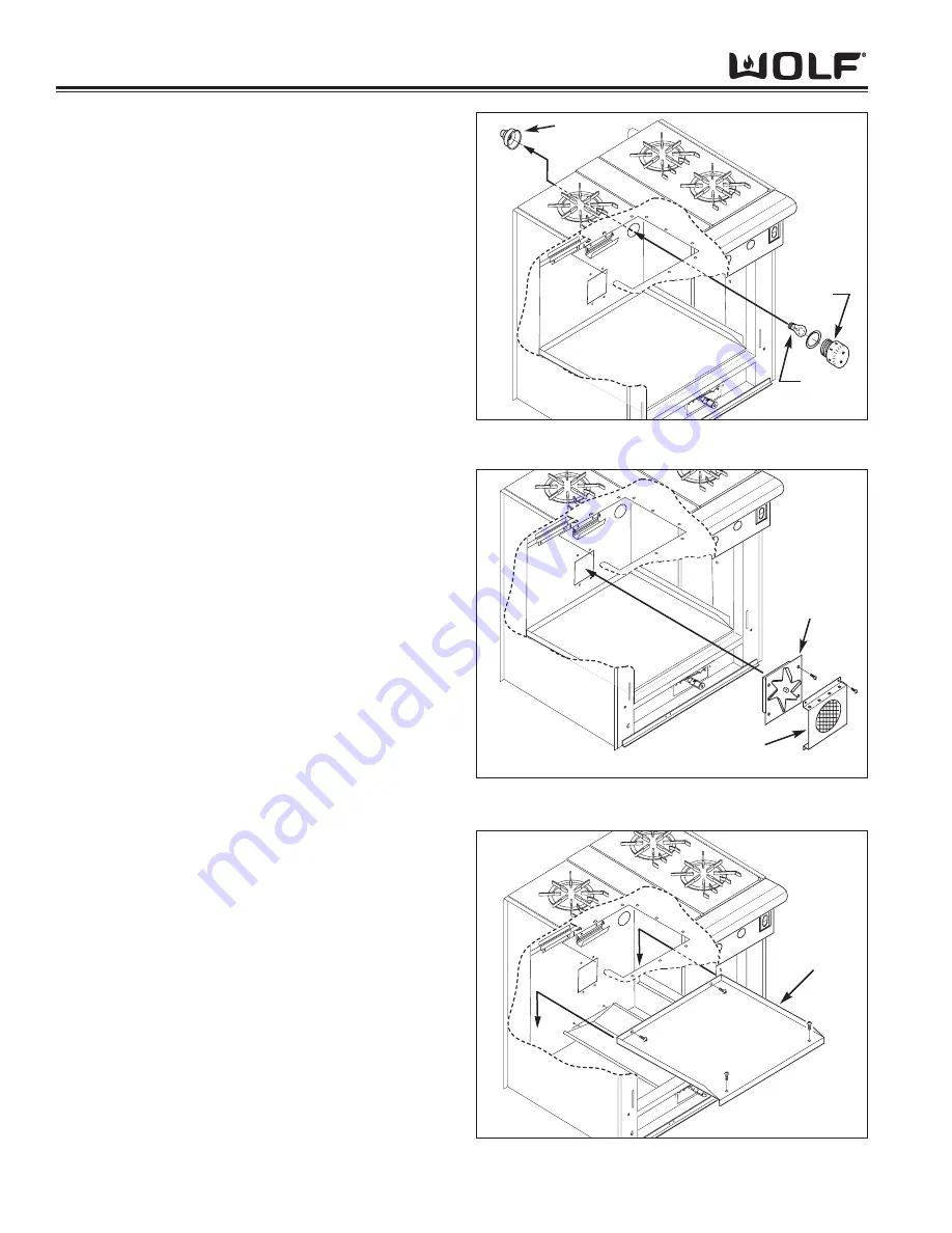
Oven Light Components Removal
To access and remove the light components, begin by
unscrewing the light lens. The light bulb can now be
removed by unscrewing it from the light socket. (See
Figure 3-29)
In order to remove the light socket, the unit must be
pulled from its installation and the back panel removed.
Then, disconnect the electrical leads from the socket
terminals. With a small flat-blade screwdriver gently
expand the metal tabs on each side of the ceramic
socket and pull the socket out of the lamp base. (See
Figure 3-29)
Oven Convection Fan Removal
The convection fan assembly is held to the back wall
with screws. The fan cover is positioned in front of the
fan assembly and also held to the back wall with
screws.
To remove the fan assembly, first extract the fan cover
mounting screws and pull the cover from the oven.
Then, extract the fan assembly mounting screws and
pull the fan assembly forward slightly. Disconnect the
fan’s electrical leads and pull the fan assembly from the
oven. (See Figure 3-30)
Oven Bottom Panel Removal
To remove the bottom oven panel, extract the screws at
the front and back, then lift the panel up and out of the
oven. (See Figure 3-31)
Figure 3-29. Light Components Removal
Socket
Lens
Bulb
Figure 3-30. Convection Fan Removal
Fan
Assembly
Fan Cover
Figure 3-31. Bottom Panel Removal
Bottom
Panel
Содержание RT362F
Страница 2: ......
Страница 3: ...General Information RANGES R RANGETOPS 1 1 SECTION 1 GENERAL INFORMATION ...
Страница 13: ...Theory of Operation 2 1 RANGES R RANGETOPS SECTION 2 THEORY OF OPERATION ...
Страница 20: ...RANGES R RANGETOPS Theory of Operation 2 8 ...
Страница 21: ...Installation Information RANGES R RANGETOPS 3 1 SECTION 3 INSTALLATION INFORMATION ...
Страница 26: ...RANGES R RANGETOPS Installation Information 3 6 ...
Страница 27: ...Component Access Removal 4 1 RANGES R RANGETOPS SECTION 4 COMPONENT ACCESS AND REMOVAL ...
Страница 43: ...Troubleshooting Guide 5 1 RANGES R RANGETOPS SECTION 5 TROUBLESHOOTING GUIDE ...
Страница 53: ...Technical Data 6 1 RANGES R RANGETOPS SECTION 6 TECHNICAL DATA ...
Страница 56: ...RANGES R RANGETOPS Technical Data 6 4 ...
Страница 57: ...R RA AN NG GE ES S R RA AN NG GE ET TO OP PS S Wiring Diagrams 7 1 WIRING DIAGRAMS SECTIO N 7 ...
Страница 88: ...R RA AN NG GE ES S R RA AN NG GE ET TO OP PS S 7 32 Wiring Diagrams ...


